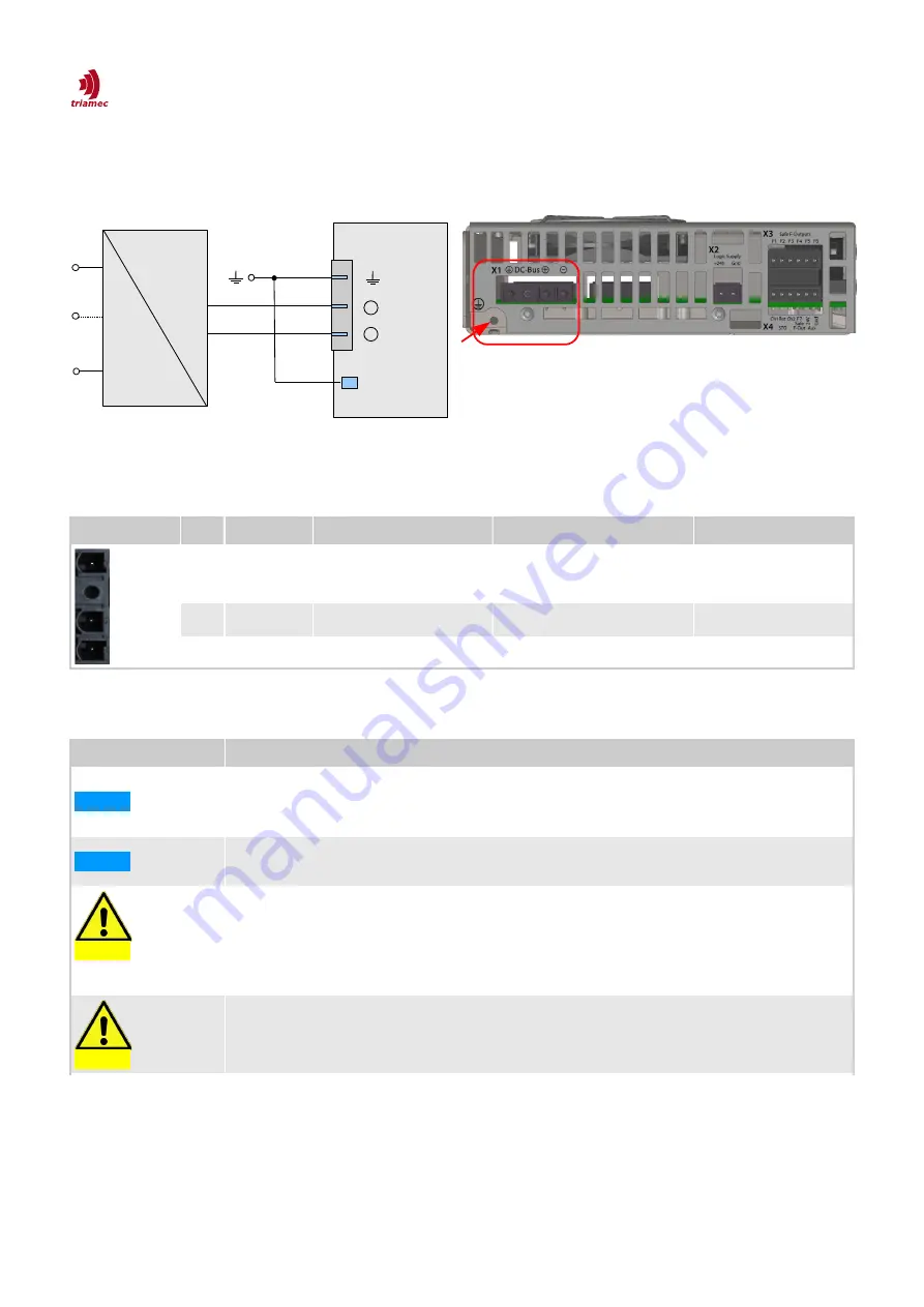
7.4.2 DC-Bus (X1)
The drive must be supplied with a DC voltage source as specified in chapter 5.2.1. Use the DC-bus con-
nector X1 at the top side of the drive. There must be two protective earth connections.
Pin Layout X1 Pin
Name
Description
Cross-Section of Wire
Maximum Current
1
PE
Protective earth
Same or larger than DC-Bus
2
+DC-Bus
DC- Bus positive voltage 1.5mm
2
min, 2.5mm
2
typ
20 Arms
3
-DC-Bus
DC-Bus ground
1.5mm
2
min, 2.5mm
2
typ
20 Arms
Table 18: Pin out DC-Bus connector.
Information
NOTICE
The Triamec Motion AG power supplies TP80 and TP130 complement these drives that do not
include an integral power supply. Its recommended to use the Triamec power supplies, see
also chapter 5.2.3 on EMC.
NOTICE
Power supply always must be galvanically isolated from the supply mains to comply with isola-
tion requirements according to EN 61800-5-1.
CAUTION
Hot-plugging of the DC-bus link connector is strictly forbidden. The servo drives have large in-
ternal capacitors. It is therefore also forbidden to have a simple power-switch or relay in the
DC-bus link, because this will also cause large inrush currents.
A power-switch or relay in the DC-bus link is allowed only, if it has a soft-start functionality as
supplied by the Triamec power supplies TP80 and TP130.
CAUTION
Please note if not using a Triamec power supply: The servo drives have no built in brake-resis -
tor. When decelerating a mechanical load, currents can get negative, refer to chapter 5.4.
HWTSD80-TSD130_4_HardwareManual_EP006
2022-01-27
30/49
Figure 10: DC-Bus connection.
Figure 9: DC-Bus connector (X1).
1
2
3
DC-Bus
Power Supply
=
~
X1
-
+
-
+
1
2
3
PE


