70
Differentiator Gain Limit
The differentiation control reacts to the rate of change of the error
between the setpoint and the feedback signal. This is seldom needed
for HVAC applications. If the differentiation function becomes too
dominant, the differentiation factor can be limited. This is done in
parameter 426,
PID Differentiator Gain Limit
.
Lowpass Filter
Noise on the feedback signal can be reduced by using the built-in
lowpass filter. Set a suitable lowpass filter time constant. This time
constant determines the cutoff frequency of the filter.
If the lowpass filter has been set to 0.1s, the cut-off frequency will be 10
RAD/sec., corresponding to (10/2 x
π
) = 1.6 Hz. This means that any
noise on the feedback signal whose frequency is greater than 1.6 Hz
will be filtered out. Choose a suitable time constant in parameter 427,
PID Lowpass Filter Time
.
Optimization of the Process Regulator
The basic settings have now been made; all that remains to be done is
to optimize the proportional gain, the integration time and, if needed, the
differentiation time. These are set by parameters 423, 424 and 425. In
most processes, this can be done by following the guidelines below.
1. Start the motor.
2. Set parameter 423,
PID Proportional Gain,
to 0.3 and increase it
until the feedback signal becomes unstable. Then reduce the
value until the feedback signal has stabilized. Now lower the
proportional gain by about half (40% to 60%).
3. Set parameter 424,
PID Integration Time,
to 20 seconds and
reduce the value until the feedback signal becomes unstable.
Increase the integration time until the feedback signal stabilizes.
Now increase the integration time from 15% to 50%.
4. Parameter 425,
PID Differentiation Time,
is only used in very
fast-acting systems and should be left off for most HVAC applica-
tions. When it is used, the typical value is 1/4th the value set in
parameter 424,
PID Integration Time
. The differentiator should
only be used when the setting of the proportional gain and the
integration time have been fully optimized.
Starting and stopping the drive will produce the necessary error signal
in the process to set the PID.
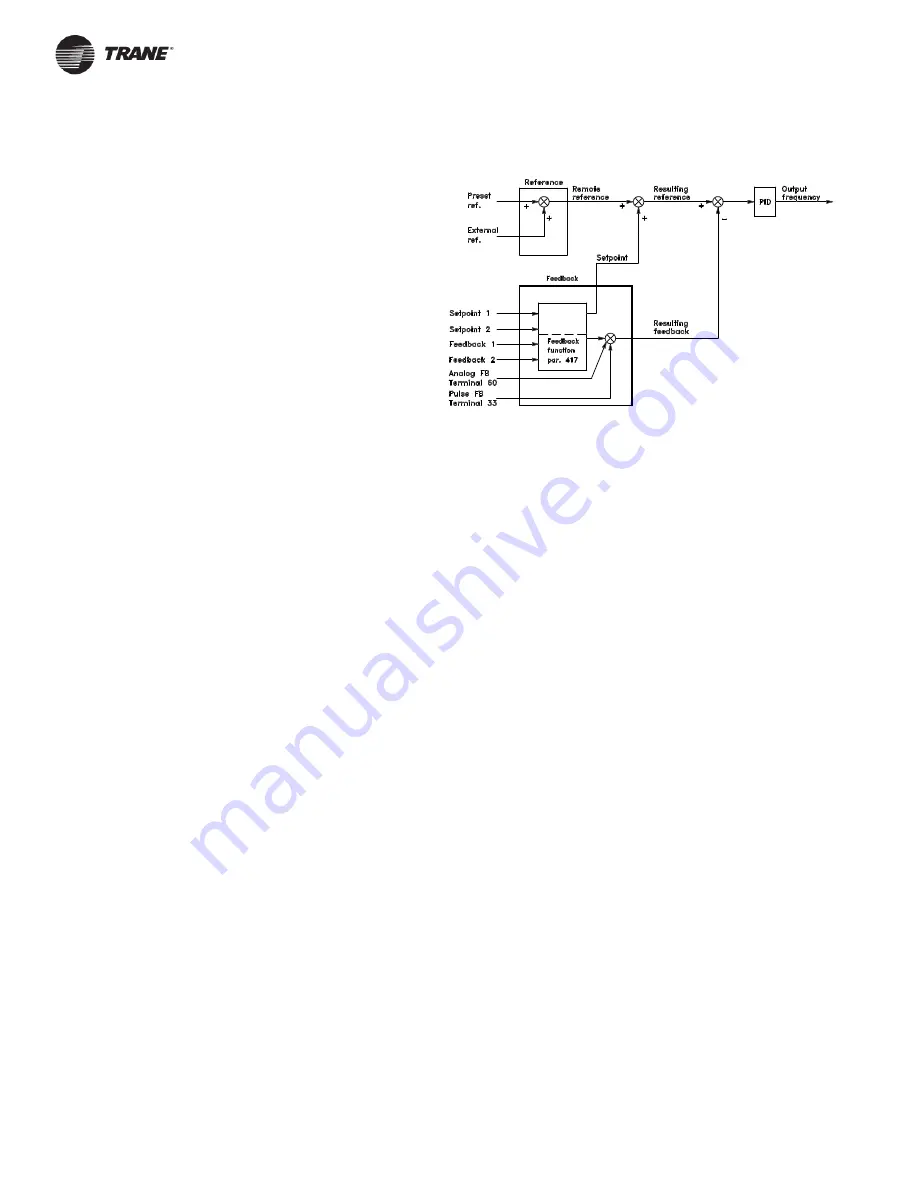
PID Overview
The block diagram below shows reference and setpoint in relation to
the feedback signal.
As can be seen, the remote reference is added to Setpoint 1 or
Setpoint 2. The setpoint that is active depends on the value of
parameter 417,
Feedback Function
.
Feedback Handling
Handling of the feedback signal(s) can be seen from the block diagram
on the next page. The block diagram shows how and by which
parameters the feedback handling is affected.
Feedback signals can be voltage, current, pulse and bus feedback
signals. In two zone feedback systems, both feedback signals must be
voltage signals (terminals 53 and 54). Please note that
Feedback 1
consists of bus feedback 1, (parameter 537) added to the feedback
signal value of terminal 53.
Feedback 2
consists of bus feedback 2,
(parameter 538) added to the feedback signal value of terminal 54.
In addition, the drive has an internal calculator capable of converting a
pressure signal into a linear flow feedback signal. This function is
activated in parameter 416,
Feedback Conversion.
The parameters for feedback handling are active both in closed and
open loop modes. In open loop, the feedback signal can be displayed
on one of the drives meters and the drive can produce warnings if the
feedback signal is beyond the range set in parameters 227,
Warning:
Low Feedback
and 228,
Warning: High Feedback
.


