18
Control Connections
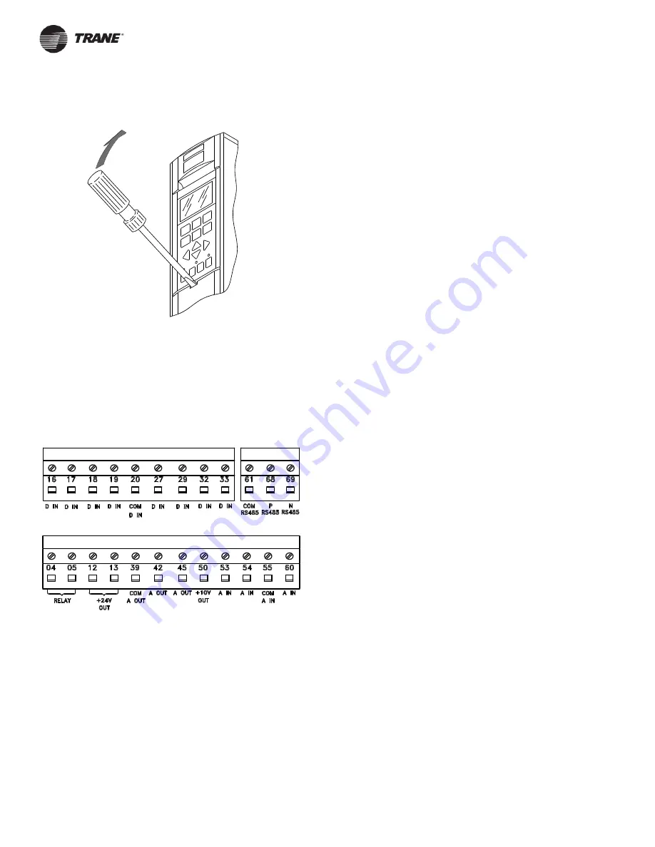
All terminals for the low voltage control wires are located under the
protective cover below the keypad. Remove the cover with a
screwdriver or other pointed object as shown bellow.
Electrical Installation, Control Terminals
Torque control terminals to 5 in-lbs (0.5-0.6 N-m)
Max. wire size: 16 AWG (1.5mm
2
)
The diagram below shows the location of the control terminals. The
programming section of the manual covers the programmable terminals
in greater depth.
Drive Inputs and Outputs
The drive operates by receiving control signals. Control input gets to
the drive in three possible ways. One way is from input signals through
the wiring connected to the drive control terminals. The drive control
terminals are located below the LCP keypad.
Another control source is through serial communication from a serial
bus. A serial communication protocol supplies commands and
references to the drive and reads status and data from the drive. The
serial bus connects to the drive through the RS-485 serial port. Use of
serial communication may require installation of a corresponding option
card.
A building management system, remote sensors, a speed command
from associated equipment, or a PLC (programmable logic controller)
are examples of possible remote drive controllers.
The third way for drive control input is through the keypad on the front
of the drive when operating in local (hand) mode. These inputs include
start, stop, reset, and speed reference.
Input Signals
The drive can receive two types of remote input signals: digital or
analog. Digital inputs are wired to terminals 16, 17, 18, 19, 20
(common), 27, 29, 32, and 33. Analog inputs are wired to terminals 53,
54, and 55 (common), or terminal 60.
Analog signals can be either voltage (0 to +10 VDC) connected to
terminals 53 and 54, or current (0 to 20 mA or 4 to 20 mA) connected
to terminal 60. Analog signals can be varied like dialing a rheostat up
and down. The drive can be programmed to increase or decrease
output in relation to the amount of current or voltage. For example, a
sensor may supply a variable current. The drive output, in turn,
regulates the speed of the motor connected to the drive in response to
that analog signal.
Digital signals are a simple binary 0 or 1 which, in effect, act as a
switch. Digital signals are controlled by a 0 to 24 VDC signal. A voltage
signal lower than 5 VDC is a logic 0. A voltage higher than 10 VDC is a
logic 1. Zero is open, one is close. Digital inputs to the drive are
switched commands such as start, stop, reverse, coast, reset, and so
on. (Do not confuse these digital inputs with serial communication
formats where digital bytes are grouped into communication words and
protocols.)
The RS-485 serial communication connector is wired to terminals (+)
68 and (-) 69. Terminal 61 is common and may be used for terminating
shields only when the control cable is run between VLT drives, not
between drives and other devices.


