background image

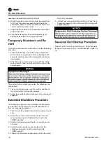
sor, steadily remove the compressor from the base 
frame with a forklift which should support the weight 
of the compressor.

6. Take samples of the collected oil for analyses. If the

oil has deteriorated, completely drain and weight the
oil inside the oil separator and oil pipes.

7. Install the new compressor. Reinstall all pipelines,

connections, wires, and screws/bolts. Open the main-
tenance (service) valves.

8. Reassemble the vertical pillar.
9. Vacuum and recharge the oil and refrigerant after

performing the leak tests.

Note: 

the weight of oil charged = the weight of oil have 
d 0.8kg.

10. Power on for trial running. Check the suction and

discharge pressure of compressor whether within the
range of 

Table 10

 after the compressor has stabilized

its operation.

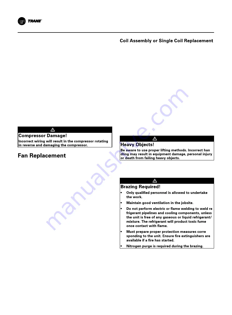
 WARNING

Fan replacement should follow the procedures listed 
below:    
1. Disconnect and lock power supplies.
2. Disconnect wiring in the terminal box of malfunc-

tioned fan.

3. Remove the 

fi

xing bolts of the guard and ori

fi

ce of

malfunctioned fan.

4. Dismantle the components of the malfunction fan

and replace with a new set, tighten the surrounding

fi

xing bolts of the guard.

5. Reconnect the electrical wirings. Ensure the line

marks are correct and the seal ring should cover on
the electrical wirings without wrinkle. The wirings
should be 

fi

xed on the guard with cable ties.

Note: 

The water-proof nuts of fan terminal box should 
be tightened to prevent short circuit from mois-
ture.

6. Con

fi

rm the fan blades can freely rotate before pow-

er on for trial running.

7. Con

fi

rm the correct fan rotation after running.

Coil replacement should follow the procedures:
1. Disconnect and lock power supplies.
2. Recover the refrigerant.
3. After the pressure in system has been completely

released, disconnect the gas and liquid connection
pipe of the coil.

4. Open the control panel, disconnect the fan power ca-

ble from the contactor, and remove the fan assembly
on the coil to be replaced.

Note 1: For single coil replacement, may not need
this step.
Note 2: Record the connection position before dis-
connect.

5. Fix the coil to the lift through lifting holes on the top

metal plate of coil. The lifting capacity of each rope
must exceed the published weight of coil.

6. Remove the malfunction coil stably and replace with

a new one.

 WARNING

-

7. Weld the connecting pipes of new coil, and imple-

ment pressure leakage test, then reinstall the metal
plates.

 WARNING

-

-

8. Vacuum and recharge the refrigerant
9. Power on for trial running. Check the evaporator ap-

proach and condenser approach whether within the
range of 

Table 39

 after the compressor run stably.

Maintenance Procedures

116


RTAG-SVX001H-EN

Содержание RTAG 225

Страница 1: ...1H EN Models RTAG 225 500 ton units 60Hz Feb 2022 572598690001 SAFETY WARNING Installation Operation and Maintenance RTAG Air Cooled Helical Rotary Liquid Chillers Confidential and proprietary Trane i...

Страница 2: ...result in equipment or property damage only Scientific research has shown that certain man made chemicals can affect the earth s naturally occurring strato spheric ozone layer when released to the at...

Страница 3: ...N March 2022 New manual Unchanging refrigerant before welding filled with nitro gen for protection and use cooling method to protect ing the electron component TRANE is not responsible for the equipme...

Страница 4: ...lifting schematic 4 points 26 Figure 11 Unit lifting schematic 6 points 26 Figure 12 Unit lifting schematic 8 points 26 Table 7 Lifting Weights and CG Dimensions 27 Isolator Installation 28 Figure 13...

Страница 5: ...urations 47 BACnet Protocol 50 Object Data Points and Diagnostic Data Points with Corresponding Chiller Models 50 Table 20 Analog Output 50 Table 21 Analog Input 51 Table 22 Multistate Output 51 Table...

Страница 6: ...quence of events power up to starting 71 Stopped to Starting 72 Figure 52 Sequence of events stopped to starting 72 Running Lead Compressor Circuit Start and Run 73 Figure 53 Sequence of operation run...

Страница 7: ...Separator Oil Level Check 111 Figure 71 Oil Level Measure of Oil Separator 111 Compressor Oil Charging 111 Figure 72 Oil Charge of Compressor 112 Draining Compressor oil 112 Oil Loss Troubleshooting...

Страница 8: ...Troubleshooting 127 Symptoms and Diagnostics 131 Maintenance 132 Function code 133 Contents RTAG SVX001H EN 7...

Страница 9: ...d wrap M Low noise night noise set back N Standard Ambient 14 F 114 8 F 10 C 46 C H High Ambient 14 F 125 F 10 C 52 C S Single Relief Valve D Dual Relief Valve With 3 Way Valve X No Flow Switch F Fiel...

Страница 10: ...in options implementation scheme Medium low noise option of Sound Treatment use sound wrap depends compressor configuration N5 N6 use tube sound wrap N6E2 use compressor sound box this option is only...

Страница 11: ...50Hz 093 093 kW N1 50Hz 077 077 kW M2 50Hz 065 065 kW M1 50Hz 058 058 kW L2 50Hz 048 048 kW L1 50Hz 041 041 kW K2 50Hz 036 036 kW K1 50Hz A High Volume Ratio 10 RTAG SVX001H EN N Low Volume Ratio CHHW...

Страница 12: ...ail measurement for the application of exceed these limitation and other information please refer to the drive section And variable speed unit Total Harmonic Distortion of Current at rating point full...

Страница 13: ...been open to look at it oil separator nameplate stick on oil separator shell Unit nameplate include following information as Figure 1 Unit Nameplate Model number Serial number Nominal tonnage Compres...

Страница 14: ...786 995 1102 1146 1295 1390 1518 1571 Water storage lb 263 289 265 301 301 332 369 455 578 tube size inch 6 8 6 Fan type Quantity 12 14 14 16 16 18 18 20 28 power 1 5 1 65 Fan speed RPM 910 200 970 20...

Страница 15: ...38 442 447 4 7 4 7 4 7 4 7 4 7 4 7 3 8 Control panel 2 A 222 222 222 410 438 442 447 Unit start up amps Control panel 1 A 441 447 560 596 596 560 588 592 447 Control panel 2 A 222 222 222 560 588 592...

Страница 16: ...l Control panel 1 Control panel 2 Unit start up amps Control panel 1 Control panel 2 Refrigerant charge ckt 1 ckt 2 Oil charge the oil type show on unit nameplate ckt 1 ckt 2 Dimension Length Width He...

Страница 17: ...it Max RLA Max Compr Fan Control Control panel 1 Control panel 2 Unit start up amps Control panel 1 Control panel 2 Refrigerant charge ckt 1 ckt 2 Oil charge the oil type show on unit nameplate ckt 1...

Страница 18: ...flow Fan current Unit Max RLA Max Compr Fan Control Control panel 1 Control panel 2 Unit start up amps Control panel 1 Control panel 2 Refrigerant charge ckt 1 ckt 2 Oil charge the oil type show on un...

Страница 19: ...fting Point Installation Installation Point Control Panel TD7 Unit Water Box H1 mm H2 mm W1 mm W2 mm L1 mm L2 mm Water pipe L High eff Extra eff mm L Premium Seasonal eff mm RTAG225P 150psi 450 465 12...

Страница 20: ...Dimension Unit Water Box H1 mm H2 mm W1 mm W2 mm L1 mm L2 mm L mm Water pipe RTAG 230P 150psi 450 465 1275 970 5118 5118 8732 6 Figure 3 Dimension RTAG 230 Premium efficiency unit RTAG SVX001H EN 19...

Страница 21: ...Water Box H1 mm W1 mm L1 mm L2 mm Water pipe L High eff mm L Premium Seasonal eff mm 285P 150psi 450 1120 2698 1593 6 9246 Figure 4 Dimension RTAG 285 Premium efficiency unit 20 RTAG SVX001H EN Dimen...

Страница 22: ...W1 mm L1 mm L2 mm Water pipe L High eff Extra eff mm L Premium Seasonal eff mm 310P 150psi 450 1120 3877 1593 6 10418 150psi 450 1120 3877 1593 6 10418 340P Figure 5 Dimension RTAG 310 340 Premium eff...

Страница 23: ...et Side View Back View With near side control panel removed Locate Customer Power TD7 Control Panel Dimension Compressor1B Compressor1A Compressor2A Compressor2B Unit Water Box H1 mm W1 mm L1 mm L2 mm...

Страница 24: ...mm W1 mm L1 mm L2 mm Water pipe L High eff Extra eff mm L Premium Seasonal eff mm 150psi 453 1120 3582 3582 8 11875 440P 500H Figure 7 Dimension RTAG 440 500 High Premium efficiency unit RTAG SVX001H...

Страница 25: ...Pre installation the contractor must realize the following items Build a sufficient bearing rigidity smooth installa tion platform as Figure 8 to support the equipment operation weight If unit is ship...

Страница 26: ...assuring a sufficient flow of air across the condenser heat transfer surface Two detrimental conditions are possible and must be avoided if optimum performance is to be achieved warm air recirculatio...

Страница 27: ...sling and the hori zontal plane is 60 follow the Figure 10 Figure 11 Figure 12 and Table 9 3 Make sure each cord and lifting plug capability is bigger than unit shipping weight 4 Protect the coil sur...

Страница 28: ...opposite E F F at opposite A B B at opposite X Z Y C D D at opposite E F F at opposite G H H at opposite A B B at opposite X Z Y Figura 10 Unit lifting schematic 4 points Figura 11 Unit lifting schem...

Страница 29: ...1217 310 Premium 712 860 1494 1477 774 901 913 1249 8378 5136 943 1198 340 Premium 714 862 1496 1479 776 903 915 1251 8394 5136 943 1198 375 Premium 1029 1277 1386 1313 1000 1159 1342 1057 9562 5871 9...

Страница 30: ...n sound emissions should always be considered Since the environment in which a sound source is located affects sound pressure unit placement must be carefully evaluated The optional isolator is rubber...

Страница 31: ...fans isolator location 16 fans isolator location W2 W1 W3 W5 W4 W6 W8 W6 W4 W2 W5 W7 W3 W1 W8 W6 W4 W2 W5 W7 W3 W1 W8 W6 W4 W2 W9 W5 W10 W3 W1 W7 X Y X Y X Y Control Panel Not for 6 fans 18 fans isol...

Страница 32: ...t Isolator location at X axis mm Isolator Quantity W1 2 W3 4 W5 6 W7 8 W9 10 W11 12 W13 14 W15 16 225P 12 700 2150 3000 4450 6300 10 375P 400H 400P 500H 20 1100 2000 2950 4300 7496 8846 9796 10696 14...

Страница 33: ...d Brown Brick red Brick red Brick red Brick red Brick red Brick red 11 400H Brown Brown Brown Brick red Brick red Brick red Brick red Brick red Brick red Brick red Brick red Brick red Brown 13 375P 40...

Страница 34: ...d impurity Installation Mechanical entering into system Filters screen shall not be less than 20 meshes 5 install balance valve on outlet water pipe to adjust water flow rate and install service valve...

Страница 35: ...ccessories its general installation require ments outlined below see Figure 16 Shall be vertically installed in horizontal pipelines or installed on the vertical tube upward flow direction Please keep...

Страница 36: ...700 800 900 1000 water pressure drop psi water ow rate gpm EVAP WATER SIDE PRESSURE DROP 2 PASS 225P 230P 0 2 4 6 8 10 12 14 16 18 20 300 500 700 900 1100 1300 1500 1700 water pressure drop psi water...

Страница 37: ...factory installed heaters and insulated on the packaged unit evapora tor and will help protect it from freezing in ambient temperatures down to 20 F 29 C control panel does not check the electric hea...

Страница 38: ...2B XLRA Comp1A Com p1B Comp2A Com p2B YLRA Comp1A Com p1B Comp2A Comp2B Qty Ckt1 Ckt2 kW FLA 400 380 60 3 2 4 203 203 203 203 1306 1306 1306 1306 424 424 424 424 9 9 2 4 7 400 400 60 3 2 4 192 192 192...

Страница 39: ...170 203 1306 1306 1306 1306 424 424 424 424 9 9 1 65 4 7 375 460 60 3 2 4 141 168 141 168 1065 1065 1065 1065 346 346 346 346 9 9 1 65 4 7 400 380 60 3 2 4 203 203 203 203 1306 1306 1306 1306 424 424...

Страница 40: ...priate fused disconnect switches The type and installation location s of the fused discon nects must comply with all applicable codes Entrance for income power wiring is located on the left side of th...

Страница 41: ...allation Electrical POWER WIRING POWER WIRING 115 230 VAC FIELD WIRING 115 230 VAC FIELD WIRING Lorem ipsum Figure 18 Power Entrance of fixed panel Figure 19 Power Entrance of AFD panel 40 RTAG SVX001...

Страница 42: ...p 100 Remote Display Stop 600 Stopped by Tracer 300 Low Ambi ent Run Inhibit 200 When unit stops if the evaporator inlet and outlet water temperature is lower than a certain protection set value the c...

Страница 43: ...Alarm and Status Relay Option package and assign any of the above list of events or status to each of the four relays provided with the option The relays to be pro grammed are referred to by the rela...

Страница 44: ...t Limit Setpoint that will ac cept either a 2 10 VDC default or a 4 20 mA signal The Current Limit Setting can also be set via the Tracer TU or through digital communication with Tracer Comm 3 The arb...

Страница 45: ...4 to 30F 0 1 F 0 1 C 5 56 C 10 F The values for MAXIMUM RESET for each of the reset types are Reset Type Reset Ratio Range Increment English Units Increment SI Units Factory Default Value Return 0 0...

Страница 46: ...2 5 000 FT 1525 m 16 AWG 1 5 mm2 2 000 FT 610 m 18 AWG 1 0 mm2 1 000 FT 305 m The communication link cannot pass between build ings All units on the communication link can be connect ed in a daisy cha...

Страница 47: ...ler Platform Ice Building Chiller is refrigerant circuit and Platform is control circuit Note 2 Chiller Status describes Chiller Run Mode and Chiller Operating Mode Run Modes Off Starting Running Shut...

Страница 48: ...Retrieval B T ATR B Trending viewing and Modifying Trends Internal B T VMT I B Device Management Description Supported BIBB Device Management Backup and Restore B DM BR B Device Management Device Com...

Страница 49: ...imit Deadband Limit_Enable Event_Enable Acked_Transitions Notify_Type Event_Time_Stamps Yes Yes only user created objects Analog Value Object_Name Object_Type Present_Value Status_Flags Event_State Ou...

Страница 50: ..._Value Reliability Change_Of_State_Count Elapsed_Active_Time Minimum_On_Time Minimum_Off_Time Relinquish_Default Time_Delay Alarm_Value Event_Enable Acked_Transitions Notify_Type Description Inactive_...

Страница 51: ...elay Feedback_Values Event_Enable Acked_Transitions Notify_Type Event_Time_Stamps Yes Yes only user created objects Multistate Value Object_Name Object_Type Present_Value Status_Flags Event_State Out_...

Страница 52: ...does not imply that all character sets are supported simultaneously Maximum supported string length is 64 bytes any character set Character Set Descriptions Supported ANSI X3 4 IBM Microsoft DBCS ISO...

Страница 53: ...Analog Input 49 High Side Oil Pressure Compressor 1B Pressure of the oil at the high side of the compressor 1B PSI Analog Input 56 Discharge Temp Compressor 1A Discharge temperature of compressor 1A...

Страница 54: ...mmunication Lost 4 Failed to Established 5 Waiting to Establish Multi State Input 4 Refrigerant Type Refrigerant Type 1 R 11 2 R 12 3 R 22 4 R 123 5 R 134a 6 R 407C 7 R 410A Multi State Input 5 Model...

Страница 55: ...ctive On Binary Input 5 Condenser Water Flow Status Inactive Normal Active Reduced Noise Binary Input 6 Chiller Auto Stop Command Allows the chiller to run if conditions for running are met Inactive N...

Страница 56: ...ve two terminals Field wired if used 3 LINK for BACnet MS TP or MODBUS Slave two terminals Field wired if used 4 Machine bus for existing machine LLIDs IPC3 Tracer bus 19 200 baud IPC3 Bus used for Co...

Страница 57: ...K MBUS IMC The TX LED blinks green at the data transfer rate when the UC800 transfers data to other devices on the link The Rx LED blinks yellow at the data trans fer rate when the UC800 receives data...

Страница 58: ...ater Setpoint XXX X F C Chiller Load Command X X Evaporator Water Flow Status Flow No Flow Evap Entering Leaving Water Temp XXX X XXX X F C On the Reports screen touch Operating Modes to view the curr...

Страница 59: ...Delay Timer to expire Chilled Water Control Chiller is running to provide a chilled water temperature per the active chilled water setpoint may be as arbitrated from various sources For cooling only...

Страница 60: ...Compressors Available The circuit cannot run because necessary compressors are being prevented from running Auto The circuit is not currently running but can be expected to start at any moment Calibra...

Страница 61: ...uction saturated temperature exceeds the Hot Start Threshold Temperature at the point at which the step load for the respective circuit would be de sired This is often the case in a high water tempera...

Страница 62: ...er display to view a variety of re ports and to create and edit a custom report All reports contain live data that refreshes every 2 5 seconds Touch the Reports button in the main menu area Figure 23...

Страница 63: ...XXX X F C Oil return Solenoid Valve CprsrXA Open Closed Oil return Solenoid Valve CprsrXB Open Closed EXV Percent Open CktX XXX X Description Resolution Units Outdoor Air Temperature XXX X F C Percent...

Страница 64: ...L2 Starter XX XXX X Amps Motor Current L3 Starter XX XXX X Amps Motor Voltage AB Starter XX XXXX X Volts Motor Voltage BC Starter XX XXXX X Volts Motor Voltage CA Starter XX XXXX X Volts You can use...

Страница 65: ...e numbers to change the current value The new value appears above the keypad 3 Touch Save to complete the change The current value is updated in the upper left side of the screen demonstrating that th...

Страница 66: ...Out Locked Out Evaporator Water Pump Lockout Pump 2 Not Locked Out Locked Out Front Panel Circuit Lockout Ckt1 Not Locked Out Locked Out Front Panel Circuit Lockout Ckt2 Not Locked Out Locked Out EXV...

Страница 67: ...return to the Display Preferences screen Use the Date Format screen to choose from the follow 66 RTAG SVX001H EN ing date formats Controls MMDDYYYY default YYYYMMDD DDMMYYYY Use the Date Separator scr...

Страница 68: ...ws screen cleaning without it responding to touch During this time the screen is black with a number in the center that counts down the seconds After 5 seconds the Settings screen re appears If securi...

Страница 69: ...is a four digit number which was config ured for your system with the Tracer TU service tool b As you enter the number the PIN remains hidden 68 RTAG SVX001H EN by asterisks Note If you enter an inva...

Страница 70: ...AM minimum 1024 x 768 screen resolution Ethernet 10 100 LAN card Available USB 2 0 port Microsoft Windows 7 Enterprise or Professional operating system 32 bit or 64 bit or Windows 8 1 Important Tracer...

Страница 71: ...RTAG Sequence of Operation Chiller State Chart Controls Figure 49 Software operation overview 70 RTAG SVX001H EN...

Страница 72: ...n cylinder indicate diagnostic checks Text outside a box or cylinder indicates time based functions Solid double arrows indicate fixed timers Dashed double arrows indicate variable timers Important Se...

Страница 73: ...es Need to cool differential to start already exists Oil level is detected immediately The above conditions would allow for a minimum power up to starting the first compressor time of about 45 sec ond...

Страница 74: ...following conditions No motor restart inhibit time left from subsequent starts Evaporator Water flow occurs quickly with pump on command Need to cool differential to start already exists The above con...

Страница 75: ...Figure 53 shows a typical start and run sequence for the lead compressor and its circuit Controls Figure 53 Sequence of operation running lead compressor circuit start and run 74 RTAG SVX001H EN...

Страница 76: ...Condenser Fans for Optimum Differential Pressure Enforce All Running Mode Diagnostics for Chiller Lead Compressor and its Circuit Modulate Compressor for Limit Control Modulate Compressor for Capacity...

Страница 77: ...mination Pressure setting OR LERTC saturated pressure 32F which ever is greater The condenser compressor discharge pressure exceeds 315psia The compressor pressure ratio exceeds 12 3 The system differ...

Страница 78: ...Figure 56 shows the normal transition from full load to minimum load while the chiller is running Figure 56 Sequence of events Unloading unstaging RTAG SVX001H EN 77...

Страница 79: ...ning through a Normal friendly shutdown The dashed lines on the top at tempt to show the final mode if you enter the stop via various inputs Controls Figure 57 Sequence of events normal shutdown to st...

Страница 80: ...om Running through an immediate shutdown The dashed lines on the top attempt to show the final mode if you enter the stop via various inputs Figure 58 Sequence of events immediate shutdown to stopped...

Страница 81: ...as a special action defined in the table below it will be displayed only as Informa tional Warning as long as no circuit or chiller shutdown results If there is a shutdown and special action defined i...

Страница 82: ...Must Trip time from the transition command is 6 seconds Actual design is 2 5 seconds This diagnostic is active only for Y Delta Auto Transform er Primary Reactor and X Line Starters Local Phase Revers...

Страница 83: ...ng Y Delta Starters Only made to ensure that there are no cur rents detected by the CT s If currents at start then one of the other contac tors is shorted Local Starter Fault Type II xy Cprsr Immediat...

Страница 84: ...110 or less for 10 continuous seconds Remote Under Voltage Chiller Normal NonLatch Pre Start and Any Ckt s Energzd Nom trip 60 seconds at less than 87 5 2 8 at 200V 1 8 at 575V Auto Reset at 90 or gr...

Страница 85: ...pressor distinguishing a liquid Local Loss of Oil for Com pressor Stopped Circuit Immediate and Special Action Latch Compressor Pre start all other modes Oil Loss Level Sensor detects a lack of oil in...

Страница 86: ...eat will be ignored for 5 minutes Remote Compressor Dis charge Refrigerant Temperature Sensor xy Cprsr Immediate Latch All Bad Sensor or LLID Remote Restart Inhibit In voked xy Cprsr Warning NonLatch...

Страница 87: ...e Sensor Circuit Immediate Latch All Bad Sensor or LLID Remote Suction Refrigerant Pressure Sensor xy Cprsr Immediate Latch All Bad Sensor or LLID Remote Evaporator Refrig erant Pool Tempera ture Sens...

Страница 88: ...rtup Period expires The Suction Pressure fell below 16 Psia Local Very Low Evapora tor Rfgt Pressure xy Chiller Immediate Latch All The respective circuit s evaporator pres sure dropped below 80 of th...

Страница 89: ...ntil diagnostic auto resets then return to normal evap pump control and de energize the Freeze Avoidance Re quest Automatic reset occurs when the respective Evap Rfgt Pool Temp rises 4 F 1 1 C above t...

Страница 90: ...ingle inverter dual redundant pump can only happen after the fault is cleared Local Evap Pump 1 Starts Run Time Written Chiller Warning NonLatch All Diagnostic is triggered when the Evap Pump 1 Starts...

Страница 91: ...essure as limited by the particular compressor type Remote Emergency Stop Feedback Input Chiller Immediate Latch All a Emergency stop feedback input is open An external interlock has tripped Time to t...

Страница 92: ...ed The presence of this software error message suggests an internal software problem has been detected The events that led up to this failure if known should be recorded and transmitted to Trane Con t...

Страница 93: ...ss Exter nal Demand Limit Setpoint Chiller Special Action Latch All Continual loss of communication be tween the MP and the Functional ID has occurred for a 30 second period Chiller shall discontinue...

Страница 94: ...atch All Continual loss of communication be tween the MP and the Functional ID has occurred for a 15 30 second period Remote Comm Loss Local BAS Interface Chiller Warning NonLatch All Continual loss o...

Страница 95: ...rred for a 30 second period Note The Subcooled Liquid Line Temperature Sensors are used for determination of charge and accurate tonnage predictions Remote Comm Loss Liquid Line Pressure Circuit Norma...

Страница 96: ...nctional ID has occurred for a 30 second period Remote Comm Loss Evapo rator Entering Water Pressure Chiller Warning Latch All Continual loss of communication be tween the MP and the Functional ID has...

Страница 97: ...efrigerant cycle of unit without economizer is represented in the pressure enthalpy diagram in Figure 60 Key state points are indicated on the figure The cycle for the full load ARI design point is re...

Страница 98: ...between the high pressure and low pressure cavities dictated by the position of the loading valve relative to the rotors When the valve slides toward the discharge end of the rotors compressor capaci...

Страница 99: ...ff Fan staging depends on the chiller load evaporator pressure condenser effec tiveness ambient temperature and numbers and sizes of fans installed on the circuit RTAG evaporator is CHIL evaporator wh...

Страница 100: ...or majority of it is separated and flow to bottom of oil separator minority enters system cir cuits with refrigerant Oil in the oil sump of separator is discharge from oil separator by high pressure w...

Страница 101: ...has been installed in a A B C phase sequence 5 Check and confirm all the fans can rotate freely 6 Fill the evaporator chilled water circuit Vent the sys tem while it is being filled Open the vents on...

Страница 102: ...lockwise CBA This direction may be reversed by interchanging any two of the line wires It is this possible interchange of wiring that makes a phase sequence indicator necessary if the operator is to q...

Страница 103: ...ow temperature cutouts Flow rates that are too high can cause tube erosion in the evaporator According to Figure 15 Water side heat exchanger typical piping connection schematic P 33 Measure the water...

Страница 104: ...in full load b Measure the system discharge superheat Evaporator Approach Condenser Approach Range C Calculation Method Range C Calculation Method 2 4 Leaving water tem suction temperature 12 20 Leavi...

Страница 105: ...controller receives a call for cooling and the dif ferential to start is above the setpoint 2 All system operating interlocks and safety circuits are satisfied The following procedure is to be followe...

Страница 106: ...may has leakage Please check the leakage source and repair it 4 Inspect the entire system for unusual conditions and inspect the condenser coils for dirt and debris If the coils are dirty clean the co...

Страница 107: ...p Actual Conditions Entering Water Type of Glycol GPM RLA KW Volts Glycol Entering Water Compressor D Model Serial KW Volts HZ Serial Other RLA Evap Design Conditions Compressor C Other Model Other Vo...

Страница 108: ...urn Start Reset Return Max Reset Outdoor Reset Ratio Outdoor Start Reset Outdoor Max Reset Chilled Water Pump Delay Time minutes Chilled Water Setpoint Filtering Settling Time sec Compressor Staging D...

Страница 109: ...e psid kPa Evaporator Refrigerant Pressure psig kPa Saturated Evaporator Rfgt Temp F or C EXV Position Evaporator Rfgt Liquid Level inches mm Compressor 1A Tab Compressor 1B Tab Operating Mode Hours H...

Страница 110: ...RLA Line 3 current RLA Evaporator Oil Return Solenoid open closed open closed open closed open closed open closed open closed Supply Oil Temperature F or C Intermediate Oil Pressure psig kPa Female St...

Страница 111: ...Be certain that the electrical power to the unit is discon nected before performing this procedure WARNING If there is no refrigerant in the unit it is necessary to pump the vacuum first and then ref...

Страница 112: ...ble and explosive objects rain proof and avoid to moisture When the recovery equipment is working the unit or loop recovered shouldn t run The refrigerant recovery container must be dedicated to R134a...

Страница 113: ...ether the oil return solenoid valve is open and whether the filter on oil return pipeline requires replacement If a system leak is detected repair the leakage before replenishing the oil 7 Close the s...

Страница 114: ...it has stopped 2 Once low oil level is confirmed 2kg of oil needs be added into the oil separator in unit stopped mode Then start the unit and keep running for 2 hours After stopping the unit again dr...

Страница 115: ...two ends of the filter 2 Discharge the oil and refrigerant inside the filter pipe with the pin valves on the top of ball valves 3 Replace with a new oil filter 4 Perform leak test with pressurized Nit...

Страница 116: ...ubes of water side heat exchanger requires re placement following these steps 1 With the unit off disconnect and lock unit power sup plies 2 Recover the refrigerant and confirm the pressure inside hea...

Страница 117: ...ng should cover on the electrical wirings without wrinkle The wirings should be fixed on the guard with cable ties Note The water proof nuts of fan terminal box should be tightened to prevent short ci...

Страница 118: ...two circuits include suction pipes refrigerant inlet pipes oil return pipes etc 5 Use the spars to lift and move the water side heat exchanger smoothly 6 Hoist the new water side heat exchanger into...

Страница 119: ...OUTPUT PH AC V A Hz kW S N XXXXXXXXXXXXXXXX Certificates Model Rated output Serial No Nameplate Rated input CA T TL Code Product Series CA Central air conditione r Code Description TL Trane Code Appli...

Страница 120: ...Grounding terminal Main circuit terminal Control board Power indicator Grounding screw of safety capacitor and VDR Top hanging ring Bottom hanging ring Installation rack Figure 75 Figure 76 AC drive c...

Страница 121: ...utomatically when the grid voltage changes through the permissible range Overvoltage and overcurrent stall control The system limits the output current and voltage automatically during operation to pr...

Страница 122: ...terminals Seven DI terminals with 100 Hz maximum input frequency Three AI terminals that support 0 V to 10 V 0 mA to 20 mA input and PT100 input Output terminals Four DO terminals Three relay output t...

Страница 123: ...B D dX6 H dX8 D H1 B W W1 A Model Mounting Hole mm Dimensions mm Mounting Diameter d mm Weight kg A B W W1 H H1 D CA300 4T160 TL 415 440 375 445 550 580 320 10 42 CA300 4T200 TL 594 600 550 630 700 74...

Страница 124: ...o V to mA to V to mA OP COM R S DI DI DI DI CA Fault output Frequency reference power AO External keypad interface Multifunctional open collector output M T DC reactor Three phase AC current AO AO V I...

Страница 125: ...1 and 2 AC reactor connection Connected to the DC reactor Grounding terminal Grounding ST O STO DNS DNS ST O STO Control board Contact STO board V COM STO1 and STO2 are connected by NC contacts to the...

Страница 126: ...ol Fault indicator Parameter unit indicator Increment key Shift key Stop Reset key Con rm key Decrement key Multi function selection key RPM A V Hz Function of keys on the LED operating panel Key Key...

Страница 127: ...Command source indicator LOCAL REMOT Off under operating panel control LOCAL REMOT On under terminal control LOCAL REMOT lashing under serial communication control FWD REV Running direction indicator...

Страница 128: ...ccumulative power on time and accumulative running time IGBT tempera ture and fault subcode at occurrence of the faults View this information using F9 14 1st fault type to F9 46 Fault subcode upon 1st...

Страница 129: ...t between 110 and 140 The setting of F3 20 V F current limit gain is too small Adjust it between 5 and 20 The braking unit and braking resistor are not installed Install the braking unit and braking r...

Страница 130: ...occurs on the motor Reduce load or check motor and mechanical conditions The AC drive power class is small Replace a drive of larger power class The control mode is SVC but motor au to tuning is not...

Страница 131: ...itten to EEPROM check RAM addresses and address mapping If the EEPROM chip is damaged require vendor to replace the main control board E21 02 E21 03 E21 04 E22 00 Abnormal motor auto tuning result Sta...

Страница 132: ...put cable is short circuited to ground Use a megger to measure the insulation resis tance of the motor and motor cable The AC drive is damaged Contact us or the agent 4 The display is normal at power...

Страница 133: ...t whether the running current of the AC drive exceeds the rated current of the AC drive and motor for a certain period Check whether motor parameters are set properly Check whether the motor is overlo...

Страница 134: ...04 Frequency F1 04 Frequency F1 05 Speed F1 05 Speed A4 00 1 DC power calculation enabled A4 00 1 DC power calculation enabled A4 01 97 3 A4 01 97 3 F4 01 0 tion 1 If the overtemperature connected be...

Страница 135: ...For more information please visit trane com or tranetechnologies com Trane has a policy of continuous product and product data improvement and reserves the right to change design and specifications wi...

Отзывы: