


Printed in the Federal Republic of Germany
TR-Electronic GmbH 2011, All Rights Reserved
06/28/2017
TR - ECE - BA - DGB - 0084 - 05
Page 41 of 55
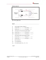
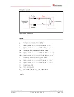
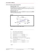
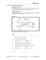
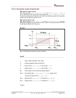
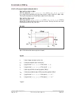
Principle schematic
Figure 4: Analog voltage output
Legend
U
O
= actual measured output voltage [V] *
U
SV
= programmed
start value
of the voltage
in mV
*
U
FV
= programmed
final value
of the voltage
in mV
*
Pos
= actual position of the measuring system [steps] *
Pos
SV
= programmed
start value
of the position
in steps
*
Pos
FV
= programmed
final value
of the position
in steps
*
n
= actual speed of the measuring system [1/Min] *
n
SV
= programmed
start value
of the speed
in 1/Min
*
n
FV
= programmed
final value
of the speed
in 1/Min
*
R
L
= Load resistor [
Ω
]
R
Line
= Line resistance [
Ω
]
R
Total
= Total resistance [
Ω
] = R
Line
+ R
L
, > 1 k
Ω
* signed