Installation / Preparation for commissioning
TR-Electronic GmbH 2011, All Rights Reserved
Printed in the Federal Republic of Germany
Page 40 of 55
TR - ECE - BA - DGB - 0084 - 05
06/28/2017
3.5 Analog – interface, basic functionalities
3.5.1 Measuring system version with Analog-Voltage
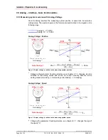
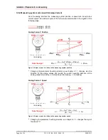
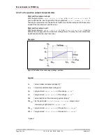
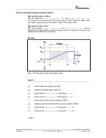
Over the analog interface the measuring system position or speed can be output as
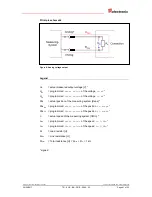
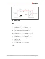
voltage value. The used acronyms in the formula are summarized in the legend on the
following page.
Analog 0…+10 VDC
Analog -10…+10 VDC
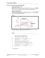
Analog Voltage / Position
Count direction:
Increasing
1)
Note the sign!
Pos =
(U
O
– U
SV
) * (Pos
FV
– Pos
SV
)
+ Pos
SV
(U
FV
– U
SV
)
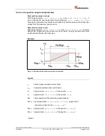
Figure 2: Output voltage in relation to the measuring system position
1)
Changing the parameter Counting direction, see chapter 4.1.1, changes also the
direction of the analog values and inverts the current counting direction at the
analog output (increasing --> decreasing or decreasing --> increasing)
Analog Voltage / Speed
Count direction:
Increasing
2)
Note the sign!
n =
(U
O
– U
SV
) * (n
FV
– n
SV
)
+ n
SV
(U
FV
– U
SV
)
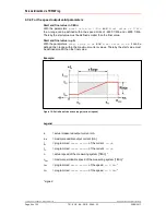
Figure 3: Output voltage in relation to the measuring system speed
2)
Changing the parameter Counting direction, see chapter 4.1.1, changes the sign of
the speed "n".

