background image

Section 5.  Troubleshooting 

Toyota Orderpicker Model 

15 Service Manual 

Troubleshooting Flowcharts 

This page intentionally left blank 

00700-CL222-05,  1 

5  March 2005 

Содержание 7BPUE15

Страница 1: ...Serial Numbers Service Manual 80 001 and up 7BPUE15...

Страница 2: ......

Страница 3: ...TOYOTA Service Manual High Level Orderpicker Model 7BPUE15 Serial No 80 001 and up 00700 CL222 05 15 March 2005...

Страница 4: ...ocopying electronic retrieval or transfer or recording without the written permission of the publisher Toyota Industrial Equipment believes the information in this manual is accurate and current as of...

Страница 5: ......

Страница 6: ...004 Improved Horn 18 SIB CE05 003 New Line Driver Assembly 6BPU15 7BPUE15 19 SIB DU01 001 New Synthetic Gear Oil 20 SIB ST06 001 Recommended Special Service Tools 21 SIB CC06 009 STM Board Improvemen...

Страница 7: ...19 Drive Unit Replacement with 360 Steer 7 TNB 2009 02 Reach Truck Steering Sensitivity 8 TNB 09 05 How to use the Toyota Service Technical Hotline 9 TNB 09 06 6BPU15 Master Cylinder Installation 10...

Страница 8: ...BPUE Caster Adjust Mast Shimming 36 HTT 2009 01 Class II Code 65 on Dispaly Card Replace 37 HTT 2009 02 No Information 38 HTT 2009 03 8BRU Drive Oil Capacity 39 HTT 2009 04 Class II Gear Case Fill Ins...

Страница 9: ...HTT 2011 06 Class II Adding Pressure Transducer Class I VI Where to Find Auxiliary Flow Rate Information 66 HTT 2011 07 Class II 8B D RU Harsh Mast Transition 8 Series Product Programming the ETAC Car...

Страница 10: ...Maintenance Guidelines 4 2 Interval 1 4 3 Interval 2 4 4 Interval 3 4 8 Troubleshooting 5 1 How to Use This Chapter 5 2 Electrical Troubleshooting Guidelines 5 3 Shorts to Frame Test 5 4 Troubleshooti...

Страница 11: ...9 Lift Motor 7 41 Steer Motor 7 42 Traction Power Amplifier 7 45 Contactors 7 46 Contactor Tip Replacement 7 48 Fuses 7 50 Circuit Cards General 7 52 Switches General 7 53 Warning Light 7 55 Hydraulic...

Страница 12: ...4 0 Theory of Operation 9 1 Battery Plugged In 9 4 Key Switch Sl On 9 10 Closing Deadman Switches 9 16 Travel 9 22 Steering 9 2 8 Lift Lower 9 34 Primary Memory 9 5 0 PinoutMatrix 9 51 Firmware Confi...

Страница 13: ...Table of Contents Toyota Orderpicker Model 7BPUE15 Service Manual This page intentionally left blank 00700 CL222 05 15 March 2005...

Страница 14: ...Toyota Orderpicker Model 7BPUE15 Service Manual Section 1 How to Use This Manual Section 1 How to Use This Manual 00700 CL222 05 15 March 2005...

Страница 15: ...nual Map of the Manual How To Use This Manual Safety rn Systems Overview I Vehicle Specifications Planned Maintenance Special Tools Troubleshooting Codes and Tests rn Go to Chart 9 Figure 1 1 Table of...

Страница 16: ...ce Q Theory of Operation Software Configuration AlphabeticalList of Component Procedures Component Location Photos Component Procedures by Lift Truck Systern Appendix I Lubrication SpecificationChart...

Страница 17: ...bleshooting is a set of decision tree charts designed to take you from a symptom to a specific sequence of tests in order to isolate a failing component The START TROUBLESHOOTING chart on Page 5 27 wi...

Страница 18: ...age Page Revision Page This section is a record of all revised pages in this manual Whenever a page is revised this section is updated and included in the revision package this lets you keep track of...

Страница 19: ...Section 1 How to Use This Manual Toyota Orderpicker Model 7BPUE15 Service Manual Page Revision Page This page intentionally left blank 00700 CL222 05 15 March 2005...

Страница 20: ...ons To examine specifications To do scheduled maintenance a problem Y e s 4 Go to Section 2 Safety Go to Section 3 Yes Systems Overview Yes Yes 1 Go to Chart 1 Figure 1 2 00700 CL222 05 15 March 2005...

Страница 21: ...icker Model 7BPUE15 Service Manual START Page Go to Section 7 inspect adjust remove install a Component Procedures Yes Yes 1 Return to 1 Figure 1 3 1 Go to Section 9 7 meoly of Operation I Go to Secti...

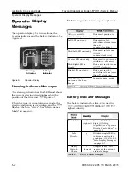
Страница 22: ...Toyota Orderpicker Model 7BPUE15 Service Manual Section 2 Safety Section 2 Safety 00700 CL222 05 15 March 2005...

Страница 23: ...of safety reminders Warning means a potentially hazardous situation exists which if not avoided could result in death or serious injury ACAUTION Caution means a potentially hazardous situation exists...

Страница 24: ...from the operator s position When elevated be sure to wear a safety belt attached to a secured tether Before working on this truck always turn the kev switch OFF and disconnect the truck s d battery...

Страница 25: ...ean up any hydraulic fluid oil or grease that has leaked or spilled on the floor a Follow exactly the safety and repair instructions in this manual Don t take shortcuts Always use and park this truck...

Страница 26: ...er Model 7BPUE15 Service Manual Section 2 Safety Do NOT add to or modify this truck until you contact your authorized Toyota Dealer to receive written manufacturer approval 00700 CL222 05 15 March 200...

Страница 27: ...and water Battery acid causes burns Should any electrolyte come in contact with your clothing or skin flush the area immediately with cold water Should the solution get on your face or in your eyes f...

Страница 28: ...s on top of the battery A short circuit or explosion could result Keep batteries clean Corrosion causes shorts to the frame and possibly sparks Keep filler plugs firmly in place at all times except wh...

Страница 29: ...Never plug a battery charger into the truck s battery connector Plug the battery charger only into the battery connector from the battery Follow the charging procedures in the Battery Instruction Man...

Страница 30: ...ics always use static discharge precautions 1 Place a static discharge wrist strap around your wrist Connect the ground lead to the wrist strap connector 2 Plug the ground cord into the ESD plug on th...

Страница 31: ...tive Work Surface Ground Cord Figure 2 3 Anti Static Kit With Wrist Strap and M a Wrist straps are availablein quantities of 25 as part number 00590 04848 71 A wrist strap tester is available as part...

Страница 32: ...he lift button raise the operator platform until you have enough clearance for your procedure 2 Place a safety stand or block between the carriage and a baseleg and carefully lower the operator platfo...

Страница 33: ...E15 Service Manual Jacking Safety Baseleg Figure 2 5 Baseleg Jacking Points 1 Place the jack at the designated jacking point See Figure 2 5 2 Jack the baseleg until you have enough clearance to replac...

Страница 34: ...t place straps through guide rollers and secure to floor proceed to step 4 3 If guide rollers used for rail guidance are not present Chock Vehicle Strap or Block Bed Chains 7 5 in 190 5cm from front e...

Страница 35: ...lift the tractor end of the truck until the drive tire is no more that 1 inch 25 4 mm off the floor 4 Tow the truck slowly in the tractor first direction Figure 2 8 Location For Release Bolts In Brak...

Страница 36: ...d remove them before you proceed with the welding operation Coating removal may be by mechanical methods chemical methods or a combination of methods Flame cutting and or welding operations should be...

Страница 37: ...Section 2 Safety Toyota Orderpicker Model 7BPUE15 Service Manual Welding Safety This page intentionally left blank 00700 CL222 05 15 March 2005...

Страница 38: ...Toyota Orderpicker Model 7BPUE15 Service Manual Section 3 Systems Overview Section 3 Systems Overview 00700 CL222 05 15 March 2005...

Страница 39: ...load capacity Alternate load capacity Gradability Battery weight for alternate load capacity Battery weight Battery ampere hours 924 x 356 x 784 mm 108 3 in 40 in 68 75 in 31 x 13 x 30 88 in a The Mod...

Страница 40: ...ACH Tolerances 5 in 13mm b Tolerances 5 in I3mm c Tolerances 2 5 5 in 67 13 mm 88 5 95 1 0 7 1 2 7 1 4 7 88 5 95 1 0 7 2248 2413 2718 3226 3734 2248 2413 2718 1 2 3 1 3 7 1 6 1 2 0 1 2 4 1 1 8 3 204 2...

Страница 41: ...n OAW Power Unit Baselegs Safety Belt Tether 39 991mm Platform Width 2 51mm Opening J2 51mm OHG Thickness Extended 78 5 1994mm Operator Compartment 85 2159mm 7 178mm Battery Bumper to CL of Drive Tire...

Страница 42: ...l System Data Chassis Carriage DEFINITION Part of the truck that moves by hydraulic force includes operator platform Mast ss Operato Platform Bumper Baseleg Figure 3 1 Model 7BPUE1 5 Carriage View 007...

Страница 43: ...DEFINITION Holds the majority of electrical and hydraulic components of the lift truck including the power section and lift motor and pump For the location of specific components See Component Locato...

Страница 44: ...two bottom bolts 2 Remove banding forks and truck from cradle 3 Use two hoists in conjunction to stand truck upright 4 Install 2 bumper plate bolts 5 Install dipstick in drive unit 6 Remove shipping...

Страница 45: ...specific frequency and amplitude generated from the line driver Truck installed equipment includes Two guidance sensors tractor end and load end Guidance manager in tractor Filter card on guidance man...

Страница 46: ...a factory installed option that enables truck operation in temperatures of 20 F 28 86 C to 40 F 4 C On cold storage trucks the electrical panel on the tractor is completely enclosed to contain heat C...

Страница 47: ...erpicker Model 7BPUE15 Service Manual Cold Storage COLD STORAGE CARRIAGE CONTROLHANDLE JPC2 12 FU13 JPHl41 J P H I A JPH13 1 WIRES TP4 JPH122 COLD STORAGE TRACTOR Figure 3 3 Cold Storage Electrical Sc...

Страница 48: ...teria have been met by the manufacturer and tested and documented by UL EE designated trucks are electrically powered units that have in addition to all of the requirements for E and ES units electric...

Страница 49: ...dant P N 00590 46325 71 is through the four pin connector at the top a tool that allows you to use the hydraulic corner of the traction power amplifier See system independent of the lift and lower Fig...

Страница 50: ...Toyota Orderpicker Model 7BPUE15 Service Manual Section 4 Planned Maintenance Section 4 Planned Maintenance 00700 CL222 05 15 March 2005...

Страница 51: ...d with dirt or metallic particles Cold storage environments UL Label EE Perform all of the scheduled checks and maintenance at the suggested intervals See Table 4 1 on page 4 2 The time intervals give...

Страница 52: ...cy power off switch Check that the control handle returns to the neutral position when released Brake Hydraulic System I Check for oil leaks Note any unusual noise during operation and report it to th...

Страница 53: ...6 mm Page 7 28 Inspect the contactor tips for burnt or pitted surfaces Failure to replace the tips may cause surfaces to weld together causing unscheduled downtime Page 7 48 Check the plunger for smo...

Страница 54: ...es Replace defective hoses as soon as possible Inspect all fittings for leaks Repair any leaks immediately I Hydraulic Reservoir Lift Chains Check for proper fluid level and the proper fluid for the w...

Страница 55: ...r Model 7BPUE15 Service Manual Interval 2 do not reflect a normal wear pattern the chance of intermittent error codes caused by shorts between maintenance intervals It will also extend the life of cab...

Страница 56: ...Toyota Orderpicker Model 7BPUE15 Service Manual Section 4 Planned Maintenance Interval 2 Figure 4 1 Bottom of Battery Compartment 00700 CL222 05 15 March 2005...

Страница 57: ...ice Manual Interval 3 Interval 3 11 Hardware I Tighten or replace any loose broken or missing hardware I II 00700 CL222 05 15 March 2005 Drive Unit Hydraulic System Change the fluid in the drive unit...

Страница 58: ......

Страница 59: ...shooting symptom chart you may be instructed to test various electrical connector pins Use the Electrical Connector Locator Chart on Page 5 18 Every time you complete a troubleshooting procedure be su...

Страница 60: ...S1 ON This prevents accidents caused by unexpected lift truck travel Opening the Emergency Lowering Valve will prevent unexpected lihing ACAUTION Unless otherwise directed disconnect the b a e r y con...

Страница 61: ...t test light to the battery case from battery B and then to the battery case from battery B If the light lights at all even momentarily there is a serious problem with the battery either external cont...

Страница 62: ...key switch ON If the battery was previously removed ensure the battery case does not touch the truck frame 6 Use a volt ohm ammeter on the current function meter to measure leakage current to the tru...

Страница 63: ...om battery case to battery B then from case to battery B With battery connector disconnected measure leakage current from battery case to battery B and to current setting of meter then Yes I Install a...

Страница 64: ...ts one at a time measuring resistance Do NOT continue until resistance measures greater than 1000 ohms or meter damage Reconnect the battery connector Turn key switch ON Measure leakage current to tru...

Страница 65: ...ed for damage including Evidence of overheating Burned spots in the cable Nicks or cracks in the insulation Damaged or overheated terminal lugs Damaged mounting hardware or brackets Use a digital ohmm...

Страница 66: ...posed wire visible at the connectors Damaged terminations exposed wires or damaged connectors can cause operational failure of the truck During troubleshooting and repairs it is sometimes necessary to...

Страница 67: ...turned on when a magnet is positioned next to the base Keepin mind that the magnet is part of the switch assembly and can only be seen if the switch is disassembled Figure 5 2 Typical Hall Effect Swi...

Страница 68: ...caused by Bad brushes or brush springs Broken wire in the field or armature winding Loose or bad connection Refer to Figure 5 3 for the following procedure 1 Isolate the motor from the truck circuit b...

Страница 69: ...wire The result is a decrease in total resistance of the motor winding and an increase in the current flow The severity of the short circuit depends on its location A shorted motor may be indicated b...

Страница 70: ...y is at 95 With more than a 50 difference in the charge levels BDI Battery Discharge lndicator BDI resets the Operator Display to show the replacement battery s charge b Example 2 A battery in the lif...

Страница 71: ...ry is not above the configured BDI level The Operator Display continues to show 65 but then descends rapidly as the lift truck operates until the Operator Display shows the original charge of 20 Once...

Страница 72: ...ctions from one side of the fuse Use an ohmmeter set to Rxl scale and measure the resistance across the fuse The resistance should be less than 1 ohm Table 5 1 Fuse Chart 00700 CL222 05 15 March 2005...

Страница 73: ...extreme care when blocking the mast for any reason Never remove a block when it is supporting the mast Lower the carriage fully Stabilize the top of the mast with an overhead chain hoist When you meas...

Страница 74: ...ture Traction Power Amplifier Overtemperature of the traction power amplifier is 85 C 185 F and above Overheating is unusual but can occur if the traction power amplifier is installed incorrectly or o...

Страница 75: ...nnector Locator Chart Electrical Connector Locator Chart Table 5 2 Electrical Connector locator Chart JPT4 JPT5 JPT6 00700 CL222 05 15 March 2005 Sparedigital Mast limit switches lift limit switches S...

Страница 76: ...cable 1 signals Mast cable 1 power Traction power amplifier Power and drivers Steer power head connector Filter card and steer controller interface MULTI MemoryUpdate Link and Test Interface Filter c...

Страница 77: ...the PMT displays a prompt for further instruction NOTE Follow the prompt at the top of the PMT screen not the blinking icon to choose the correct setting Tool to access the diagnostic history file of...

Страница 78: ...e the tractor cover 3 Connect the PMT to the traction power amplifier 4 Connect the battery and turn the key switch ON 5 Press the test key on the PMT 6 Scroll through the line items using either scro...

Страница 79: ...ating in either the Diagnostic Mode or the Diagnostic History The messages are listed in alphabetical order for easy reference Table 5 5 Diagnostics and Special Diagnostics list 5 22 00700 CL222 05 15...

Страница 80: ...rature Throttle wiper input fault Access 1 Turn the key switch OFF and disconnect the battery connector 2 Remove the tractor cover 3 Connect the PMT to the traction power amplifier 4 Connect the batte...

Страница 81: ...er Amplifier Parameters 7 Press either change value key until the setting you want is displayed The parameter is now set at the value you selected 8 If the display stops changing and you want to go fu...

Страница 82: ...Replace drive unit Replace sealing rings bearing shims and drive shaft bearings Replace sealing rings bearing shims drive shaft bearings and drive shaft Inspect housing and drive shaft for damage Re t...

Страница 83: ...Section 5 Troubleshooting Toyota Orderpicker Model 7BPUE15 Service Manual Drive Unit Troubleshooting Guide This page intentionally left blank 00700 CL222 05 15 March 2005...

Страница 84: ...eshooting Troubleshooting Flowcharts Troubleshooting Flowcharts TS1 START TROUBLESHOOTING Message or Fault Code displayed v Yes 1M e s s E t r Code listed in symptom tables in 00700 CL222 05 15 March...

Страница 85: ...to the operator or foreman Where did it happen Operate the truck yourself if necessary and identify all components which could cause the problem What functions are affected What conditions trigger the...

Страница 86: ...of fluid Create the same conditions that occurred when the problem first happened Operate the truck as it was being operated when the problem occurred Verify the problem does not recur Have the drive...

Страница 87: ...Section 5 Troubleshooting Toyota Orderpicker Model 7BPUE15 Service Manual Troubleshooting Flowcharts This page intentionally left blank 00700 CL222 05 15 March 2005...

Страница 88: ...ailed component and flush fill and bleed the hydraulic system Lift Lower System Lift Function No Lift Motor Runs No Codes 2 Inspect L L solenoid for binding No Lift Motor Does Not Run No Codes ctor cl...

Страница 89: ...eck SG and compare to battery manufacturer s recommendations FIG until proper rollers and rails If pressure is low 1 Measure voltage to lift lower solenoid 2 Inspect L L solenoid for binding 3 Inspect...

Страница 90: ...g Symptom Tables Travel Functions Symptom Tables Travel Functions Slow or Sluggish Acceleration 1 Allow battery to set unused for two hours Check SG and compare to battery manufacturer s recommendatio...

Страница 91: ...derpicker Model 7BPUE15 Service Manual Symptom Tables Electrical Symptoms Symptom Tables Electrical Symptoms Electrical Motors Motor Overheating Dead Lift Truck Display is Dark Lift Truck is not Opera...

Страница 92: ...Toyota Orderpicker Model 7BPUE15 Service Manual Section 6 Codes and Tests Section 6 Codes and Tests 00700 CL222 05 15 March 2005...

Страница 93: ...ive unit in right zone 10 65 clockwise Drive unit in right end of travel zone more than 65 clockwise In maintenance mode Table 6 1 Steering Indicator Display Messages 11 The steering indicator has fiv...

Страница 94: ...no limit to the number of stacked codes but only the highest priority codes will be I Top LED blinking I EPO depressed Display Pull out EPO switch and reset kt switch 2nd LED from top blinking Cause D...

Страница 95: ...isplay is clear press and release the horn button once Each time you press the horn button one BDI LED lights 5 Wait for the BDI display to clear A clear display indicates the first digit was accepted...

Страница 96: ...are program See Flashware Program on page 10 2 Diagnosis Steer Encoder Test Corrective Action Step 1 2 3 4 5 6 7 8 1 Enter maintenance mode and step OFF the deadman pedal See Enter on page 6 4 Technic...

Страница 97: ...cond a heartbeat indicator A two digit flash code signals the power amplifier has detected a fault within itself The code continues flashing until corrected Figure 6 3 Traction Power Amplifier TPA Cod...

Страница 98: ...5 Service Manual Section 6 Codes and Tests TPA Code LED Solid On T P A Code LED Solid On Corrective Actions and Checks T P A Code Heartbeat Corrective Actions and Checks None System functioning proper...

Страница 99: ...el 7BPUE15 Service Manual TPA Code 1 1 TPA Code 1 l Corrective Actions and Checks TPA Code 1 2 Corrective Actions and Checks Step 00700 CL222 05 15 March 2005 1 Action Meter Setting Replace the TPA Le...

Страница 100: ...Toyota Orderpicker Model 7BPUE15 Service Manual Section 6 Codes and Tests TPA Code 1 3 TPA Code 1 3 Corrective Actions and Checks TPA Code 2 l 00700 CL222 05 15 March 2005...

Страница 101: ...Passed Step 2 TPA Code 2 6 Lead Step Failed Full speed request approx 4 25 volts No travel request 0 volts Corrective Actions and Checks Lead Action Step Meter Setting Lead Lead Replace TPA Expected...

Страница 102: ...nd S2 wires disconnected from TPA OHMs 2 S1 terminal on TPA S1 and S2 wires disconnected from TPA OHMs S2 wire Lead S2 terminal on TPA About 1 OHM Lead Step 2 Troubleshoot wires to motor and motor fie...

Страница 103: ...a blinking 4 l code This is normal operation and should not be considered a fault Corrective Actions and Checks Step 00700 CL222 05 15 March 2005 1 2 Action Meter Setting TPA Code 4 2 DCV DCV Lead JP...

Страница 104: ...ervice Manual Section 6 Codes and Tests TPA Code 4 3 Corrective Actions and Checks TPA Code 4 3 Corrective Actions and Checks been parked in a freezer for an hours take it amount of time out of the fr...

Страница 105: ...l down for a few hours Step Code clears Inspect the mounting of the TPA to the truck frame It must be tight against the from to dissipate heat properly If tight investigate the duty cycle use of the t...

Страница 106: ...Toyota Orderpicker Model 7BPUE15 Service Manual Section 6 Codes and Tests Operator Display Fault Codes Operator Display Fault Codes 00700 CL222 05 15 March 2005...

Страница 107: ...rvice Manual Code 1 3 Code 1 3 Corrective Actions and Checks NOTE Use step 1 if the contactor tips do open when the lift request is removed Use steps 2 and 3 if the contact tips do not open when the r...

Страница 108: ...on 6 Codes and Tests Code 1 4 Code 1 4 Corrective Actions and Checks NOTE Use steps 1 and 2 if the contactor tips do close when a lift is requested Use steps 3 and 4 it the contact tips do not close w...

Страница 109: ...problem with a switch or rail 2 Sol twwrc is not conligurctl correctly or is conligurctl for the wrong tr rck Looking for a switch not on the tnlck Travcl speed limited 11 P C Contactor I Closed 11 11...

Страница 110: ...tions and Checks 1 1 DCV IJPC11 2 1 JPC12 22 I B I step 2 IReplace CM Step 2 1 DCV 1 step 3 1Troubleshoot Action Meter Setting 00700 CL222 05 15 March 2005 Lead 3 4 Lead DCV DCV Expected Results JPC9...

Страница 111: ...Section 6 Codes and Tests Toyota Orderpicker Model 7BPUE15 Service Manual Code 1 8 Code 1 8 Corrective Actions and Checks 00700 CL222 05 15 March 2005 Click here for Sub Harness update info...

Страница 112: ...ns and Checks 1 1 DCV Step JPC13 7 Action Meter Setting 2 JPC13 I DCV Approx 5 volts Lead Neutral 1 0 to 2 1 volts Full F F greater than 0 4 volts Full T F less than 3 2 volts Step 2 Lead Replace CM R...

Страница 113: ...rvice Manual Code 2 2 Code 2 2 Corrective Actions and Checks Step 00700 CL222 05 15 March 2005 1 Action Meter Setting Check TPA for code displayed Lead N A Lead N A Expected Results Code Mashing Step...

Страница 114: ...Toyota Orderpicker Model 7BPUE15 Service Manual Section 6 Codes and Tests Code 2 3 Code 2 3 Corrective Actions and Checks 00700 CL222 05 15 March 2005 Click here for updated harness info...

Страница 115: ...Section 6 Codes and Tests Toyota Orderpicker Model 7BPUE15 Service Manual Code 2 4 Code 2 4 should close Corrective Actions and Checks contactor for 00700 CL222 05 15 March 2005...

Страница 116: ...ta Orderpicker Model 7BPUE15 Service Manual Section 6 Codes and Tests Code 2 5 Code 2 5 1 If the code does not clear follow the Corrective Actions and Checks Encoder at rest 0 00700 CL222 05 15 March...

Страница 117: ...ection 6 Codes and Tests Toyota Orderpicker Model 7BPUE15 Service Manual Code 2 6 Code 2 6 Corrective Actions and Checks Full lower less than 2 8 volts Full lift more than 00700 CL222 05 15 March 2005...

Страница 118: ...Toyota Orderpicker Model 7BPUE15 Service Manual Section 6 Codes and Tests Code 3 1 Code 3 l Corrective Actions and Checks disconnected 00700 CL222 05 15 March 2005...

Страница 119: ...3 Lead PT3 1 Replace STM Expected Results Prox not over metal Approx 5 volts DCV Step 4 Step Passed JPT3 1 Replace home prox sensor Step Failed At rest 4 81volts Turning tiller fast Right 0 volts Brea...

Страница 120: ...derpicker Model 7BPUE15 Service Manual Section 6 Codes and Tests Code 3 2 Turning tiller fast right 4 7 volts and Steer Power and Steer Power Motor and Troubleshoot wires to motor 00700 CL222 05 15 Ma...

Страница 121: ...V Breakout cable JPT8 10 connected between STM and Steer Power Head DCV Breakout cable JPT8 6 connected between STM and Steer Power Head DCV Breakout cable JPT8 15 connected between STM and Steer Powe...

Страница 122: ...er Model 7BPUE15 Service Manual Section 6 Codes and Tests Code 3 3 and Steer Power and Steer Power At rest 0 volts Fast turn about 1 5 volts If truck and Steer Power has a fault and will 00700 CL222 0...

Страница 123: ...7BPUE15 Service Manual Code 3 4 Code 3 4 head senses current in the steer motor circuit Corrective Actions and Checks between STM and Steer Power and Steer Power not steer test fails if jacked up DCV...

Страница 124: ...ead 1 Breakout Cable JPT8 5 connected between STM and Steer Power Head DCV Approx 4 85 volts Steering or not If low 0 volts truck thinks it is current limit and step failed Replace STM 1 Remove steer...

Страница 125: ...Section 6 Codes and Tests Toyota Orderpicker Model 7BPUE15 Service Manual Code 3 6 Code 3 6 feedback encoder circuit Corrective Actions and Checks 00700 CL222 05 15 March 2005...

Страница 126: ...Toyota Orderpicker Model 7BPUE15 Service Manual Section 6 Codes and Tests Code 3 7 Code 3 7 Corrective Actions and Checks 0 or 5 volts 00700 CL222 05 15 March 2005...

Страница 127: ...ot S23 starting with step 6 Step 10 5 to 13 volts JPC7 Disconnected DCV Step 2 Action Meter Setting PC7 2 Replace CM Lead Approx 5 volts JPC7 Disconnected DCV Step 3 Lead JPC7 I Replace CM DCV Expecte...

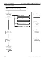
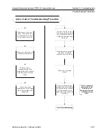
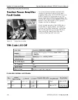
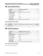
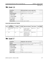
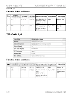
Страница 128: ...Toyota Orderpicker Model 7BPUE15 Service Manual Section 6 Codes and Tests Code 4 1 00700 CL222 05 15 March 2005...

Страница 129: ...PT12 2 closed DCV Action Meter Setting Check contactor for burnt tips and mechanical binding 0 volts when contactor should be closed B when contactor should be open Lead 0 volts when contactor should...

Страница 130: ...r Setting 3 One side of fuse DCV 4 Other side of fuse Lead DCV 0 Ohms B with tips closed 0 volts with tips open Lead B when PC should be open 0 volts when PC should be closed Step 2 Expected Results S...

Страница 131: ...teer tractor manager and it will acknowledge the message by flashing its TRANSMIT LED It is possible to determine the faulty module carriagemanager or steer tractor manager by viewing the LEDs See Fig...

Страница 132: ...Toyota Orderpicker Model 7BPUE15 Service Manual Section 6 Codes and Tests Code 4 8 Code 4 8 Corrective Actions and Checks 00700 CL222 05 15 March 2005...

Страница 133: ...sconnect all PT7 1 devices using the 12 volts on the CM DCV 10 8 to 13 volts 10 8 to 13 volts 10 8 to 13 volts 10 8 to 13 volts Replace CM Step 4 Connect devices to the STM one at a time Troubleshoot...

Страница 134: ...tive Actions and Checks Step NOTE If this code is intermittent check truck for shorts to frame and verify static straps are clean and contacting the floor 1 00700 CL222 05 15 March 2005 Action Meter S...

Страница 135: ...odes and Tests Toyota Orderpicker Model 7BPUE15 Service Manual Code 5 3 Code 5 3 Corrective Actions and Checks 12 volts on the STM one at a Troubleshoot 12 volts on the Troubleshoot 00700 CL222 05 15...

Страница 136: ...Section 6 Codes and Tests Code 5 4 Code 5 4 Corrective Actions and Checks Step 00700 CL222 05 15 March 2005 1 Action Meter Setting Load new software to the truck Lead N A Lead N A Expected Results Cle...

Страница 137: ...131313 1313131313 Corrective Actions and Checks Step NOTE If this code is intermittent check truck for shorts to frame and verify static straps are clean and contacting the floor 1 00700 CL222 05 15 M...

Страница 138: ...ilter card and JPS1 disconnected from steer controller DCV 22 to 36 volts 22 to 36 volts 10 5 to 13 volts 10 5 to 13 volts Step 2 Step 3 If Code 6 l is gone troubleshoot wires and speed encoder Is cod...

Страница 139: ...Section 6 Codes and Tests Toyota Orderpicker Model 7BPUE15 Service Manual Code 6 l disconnected that causes 12 00700 CL222 05 15 March 2005...

Страница 140: ...ive Actions and Checks the code shown on the Steer Controller card NOTE Check adjustment of the line driver Check for mechanical binding in the Drive Unit and steering gear box Run Learn for Guidance...

Страница 141: ...for mechanical binding in the Drive Unit and steering gear box Run Learn for Guidance Check setting for Heading Angle and Distance from Wire in configure If intermittent check for shorts to frame 1 0...

Страница 142: ...Toyota Orderpicker Model 7BPUE15 Service Manual Section 7 Component Procedures Section 7 Component Procedures 00700 CL222 05 15 March 2005...

Страница 143: ...Service Manual Change History Electrical Systems Page 1 of 1 Description Page Date 1 Added Drive Unit Overhaul Procedure 7 24 4 15 11 2 3 4...

Страница 144: ......

Страница 145: ...49 Inspecting 7 46 Tip Replacement 7 48to 7 49 Control Handle 7 1 7 Cover Operator Console 7 1 2 Covers and Finish Decals 7 14 Mast Guard 7 1 3 Operator Console Cover 7 1 2 Tractor Covers 7 11 Covers...

Страница 146: ...s 7 9 4 Inner Mast 7 7 8 Lift Chains 2 Stage 7 93 Lift Chains 3 Stage 7 91 Load Wheels 7 9 6 Mast Bearings 7 85 Outer Mast 7 8 1 Pallet Clamp 7 9 5 Skid Pads 7 9 7 Motor Drive 7 39 Motor Lift 7 4 1 Mo...

Страница 147: ...Section 7 Component Procedures Toyota Orderpicker Model 7BPUE15 Service Manual List of Component Procedures This page intentionally left blank 00700 CL222 05 15 March 2005...

Страница 148: ...t Procedures Component Locator Photos Component Locator Photos Side Cylinder Chains Mast Guard Page 7 91 page 7 93 Page 7 13 Side Cylinders Page 7 65 Center Cylinder Page 7 69 Forks Page 7 94 Figure7...

Страница 149: ...Model 7BPUE15 Service Manual Component Locator Photos Hydraulic Reservoir Page 7 59 Lift Motor Page 7 41 Lift Pump Page 7 62 Solenoid Valves 4 Page 7 61 Hydraulic Manifold Page 7 58 Power Cables Figur...

Страница 150: ...anual Section 7 Component Procedures Component Locator Photos Electrical Panel Cover Removed Traction Power Amplifier Page 7 45 Figure 7 3 Electrical Panel Figure 7 4 Mast Switches 00700 CL222 05 15 M...

Страница 151: ...Section 7 Component Procedures Toyota Orderpicker Model 7BPUE15 Service Manual Component Locator Photos Figure 7 5 Carriage Manager lEDs 00700 CL222 05 15 March 2005...

Страница 152: ...11 LED IL6 I IL6 2 1 Not Used I1 Representing I IL6 3 1 Hour Meter I1 I IL6 4 1 Brake I1 I IL6 5 1 Pump I1 I IL6 6 1 Horn I1 1 1L6 7 1 Lift Lower Solenoid I1 Figure 7 6 Steer Tractor Manager lEDs IL6...

Страница 153: ...Section 7 Component Procedures Toyota Orderpicker Model 7BPUE15 Service Manual Component Locator Photos Figure 7 9 Steer Power Head LED 00700 CL222 05 15 March 2005...

Страница 154: ...Press in the two latch buttons then lift the top cover straight up and out See Figure 7 10 2 Pull out the tractor cover from the top Installation 1 Position the bottom of the tractor cover inside the...

Страница 155: ...erator platform is fully lowered before placing any part of your body between the masts Figure7 1 1 Operator Console Cover Installed Removal Figure7 12 Operator Console Cover Removed 1 Lower platform...

Страница 156: ...four screws in each mounting bracket to gain clearance for mast guard 3 Lift up mast guard until notches in mast guard clear the mounting brackets 4 Pull screen guard forward to remove Installation 1...

Страница 157: ...ion to locate decals on the truck replace any decals which are damaged NOTE Clean the surface thoroughly and allow it to dry before attaching new decals Touch up the paint as required Emergency Lower...

Страница 158: ...Toyota Orderpicker Model 7BPUE15 Service Manual Section 7 Component Procedures Steering and Controls Steering and Controls 00700 CL222 05 15 March 2005...

Страница 159: ...switch OFF and disconnect battery 2 Remove operator console cover 3 Disconnect the JPC 1 from carriage manager See Figure 7 15 4 Peel failed operator display from console bezel 5 Place new operator di...

Страница 160: ...precautions against electrostatic discharge See Static Safety on page 2 9 Before disassembly determine which components require replacement Lift Lower Potentiometer Pot Lift Spring and or Horn Switch...

Страница 161: ...handle Figure7 19 Anti Rotate Tab cover 5 Make sure all wires are routed properly 5 Carefully pry the horn switch from the Tuck the common ground wire into handle cover using a small screwdriver See b...

Страница 162: ...screws from Figure 7 23 Travel Pot Bracket Screws the front of the travel pot enclosure and remove cover See Figure 7 22 Remove screws Figure 7 24 Travel Pot Enclosure Cover Removed Figure 7 22 Trave...

Страница 163: ...with the four hex head cap screws See Figure 7 22 Travel Spring and Pinion Disassembly 1 Remove the four hex head cap screws from the front of the travel pot enclosure and remove cover See Figure 7 2...

Страница 164: ...en the tangs of the potentiometer return spring 3 Rotate the lift lower knob fully counterclockwise and tighten the metal set screws to 6 to 8 in lb 0 7 to 0 9 N m 4 Check the potentiometer for proper...

Страница 165: ...re the tip is clean A dirty tip does not transfer heat well therefore requiring longer dwell time and greater tip pressure ACAUTION Contact contamination can occur if cleaning solvent is allowed to en...

Страница 166: ...Toyota Orderpicker Model 7BPUE15 Service Manual Section 7 Component Procedures Drive and Brake Drive and Brake 00700 CL222 05 15 March 2005...

Страница 167: ...ew wrench holding drive unit to tractor See Figure 7 29 8 Attach a suitable hoist to drive unit assembly and lift assembly out of truck Installation 1 Using a suitable hoist lower drive unit assembly...

Страница 168: ...Toyota Orderpicker Model 7BPUE15 Service Manual Section 7 Component Procedures 00700 CL222 05 15 March 2005 7 24a...

Страница 169: ...Section 7 Component Procedures Toyota Orderpicker Model 7BPUE15 Service Manual 7 24b 00700 CL222 05 15 March 2005...

Страница 170: ...Toyota Orderpicker Model 7BPUE15 Service Manual Section 7 Component Procedures 00700 CL222 05 15 March 2005 7 24c...

Страница 171: ...Section 7 Component Procedures Toyota Orderpicker Model 7BPUE15 Service Manual 7 24d 00700 CL222 05 15 March 2005...

Страница 172: ...Toyota Orderpicker Model 7BPUE15 Service Manual Section 7 Component Procedures 00700 CL222 05 15 March 2005 7 24e...

Страница 173: ...Section 7 Component Procedures Toyota Orderpicker Model 7BPUE15 Service Manual 7 24f 00700 CL222 05 15 March 2005...

Страница 174: ...Toyota Orderpicker Model 7BPUE15 Service Manual Section 7 Component Procedures 00700 CL222 05 15 March 2005 7 24g...

Страница 175: ...Section 7 Component Procedures Toyota Orderpicker Model 7BPUE15 Service Manual 7 24h 00700 CL222 05 15 March 2005...

Страница 176: ...Toyota Orderpicker Model 7BPUE15 Service Manual Section 7 Component Procedures 00700 CL222 05 15 March 2005 7 24i...

Страница 177: ...Section 7 Component Procedures Toyota Orderpicker Model 7BPUE15 Service Manual 7 24j 00700 CL222 05 15 March 2005...

Страница 178: ...Toyota Orderpicker Model 7BPUE15 Service Manual Section 7 Component Procedures 00700 CL222 05 15 March 2005 7 24k...

Страница 179: ...Section 7 Component Procedures Toyota Orderpicker Model 7BPUE15 Service Manual 7 24l 00700 CL222 05 15 March 2005...

Страница 180: ...Toyota Orderpicker Model 7BPUE15 Service Manual Section 7 Component Procedures 00700 CL222 05 15 March 2005 7 24m...

Страница 181: ...Section 7 Component Procedures Toyota Orderpicker Model 7BPUE15 Service Manual 7 24n 00700 CL222 05 15 March 2005...

Страница 182: ...Toyota Orderpicker Model 7BPUE15 Service Manual Section 7 Component Procedures 00700 CL222 05 15 March 2005 7 24o...

Страница 183: ...Section 7 Component Procedures Toyota Orderpicker Model 7BPUE15 Service Manual 7 24p 00700 CL222 05 15 March 2005...

Страница 184: ...Toyota Orderpicker Model 7BPUE15 Service Manual Section 7 Component Procedures 00700 CL222 05 15 March 2005 7 24q...

Страница 185: ...Section 7 Component Procedures Toyota Orderpicker Model 7BPUE15 Service Manual 7 24r 00700 CL222 05 15 March 2005...

Страница 186: ...Toyota Orderpicker Model 7BPUE15 Service Manual Section 7 Component Procedures 00700 CL222 05 15 March 2005 7 24s...

Страница 187: ...Section 7 Component Procedures Toyota Orderpicker Model 7BPUE15 Service Manual This page intentionally left blank 7 24t 00700 CL222 05 15 March 2005...

Страница 188: ...lts Removal 1 Turn steering wheel all the way to the right so you can access drive wheel mounting bolts See Figure 7 30 2 Turn key switch OFF and disconnect battery connector Use extreme care whenever...

Страница 189: ...tside of wheel is positioned upward The outside edge of hub has a chamfer to help guide new tire onto wheel The chamfered edge must always be leading edge when a tire is pressed onto hub 5 Center hub...

Страница 190: ...of the shims 7 Remove brake release screws from tractor near steer motor and install in brake Tighten screws until brake releases completely Brake Installation 1 Install brake assembly on drive motor...

Страница 191: ...uniform within 0 005 inch 0 127 mm when measured at various points around the brake When the correct air gap is obtained torque the assembly screws to 9 ft lbs 12 Nm Replace the brake friction plate i...

Страница 192: ...8mm shim between a 0 709 inch 18 mm spacer and mounting plate on each assembly screw See Figure 7 36 3 Place brake coil assembly on top of friction plate See Figure 7 36 4 Tighten assembly screws 3 Se...

Страница 193: ...Section 7 Component Procedures Toyota Orderpicker Model 7BPUE15 Service Manual Brake Drive and Brake This page intentionally left blank 00700 CL222 05 15 March 2005...

Страница 194: ...Toyota Orderpicker Model 7BPUE15 Service Manual Section 7 Component Procedures Electrical Components Electrical Components 00700 CL222 05 15 March 2005...

Страница 195: ...only one end at a time from the connector to avoid the cable ends touching and causing a short circuit Do not allow the metal cable end to touch the battery Use insulated tools and avoid contact with...

Страница 196: ...er See Figure 7 41 Replace Battery Rollers Lift the damaged roller from its slot and replace with a new one See Figure 7 41 Battery Exterior Cleaning 1 Read understand and follow procedures recommenda...

Страница 197: ...tion i h i l e it is instalied in the truck Water can seep into the electrical compartments and cause serious damage 6 Wash dirty batteries orany that have had electrolyte spilled on them with a solut...

Страница 198: ...rs Commutator Field and armature windings if accessible Motors General ACAUTION Never use a chemical solvent to clean a motor as it can carry carbon dust to inaccessible areas and cause shorts ACAUTIO...

Страница 199: ...hes This history will give you an indication of whether a brush should be changed or if it can wait until the next inspection Refer to Page 7 37 for acceptable brush length and Figure 7 47 Steer Motor...

Страница 200: ...ts holder 4 Insert a paper strip between the brush face and the commutator 5 Place a small leather loop around the coil spring for the brush If the brush spring has a loop at the brush hook the spring...

Страница 201: ...he motor should be removed for servicing Terminal Nuts Whenever you disconnect and reconnect any power leads to a motor always tighten the motor cable securing nuts with a torque wrench to prevent ove...

Страница 202: ...f truck Covers on page 7 11 2 Turn drive unit using steering wheel so installation you can reach power cables 11 Clean sealant from motor flange and cap 3 Turn key switch OFF and disconnect screws for...

Страница 203: ...15 Install cam rings if previously installed and secure motor to drive unit with cap screws 13mm socket See Figure 7 56 16 Install dipstick See Figure 7 56 17 Install steer motor and connect wires to...

Страница 204: ...t of pump Figure 7 57 before mounting to motor See Figure 7 57 lift Motor Connections Figure 7 59 2 Mount pump to motor See Figure 7 58 3 Install four bolts to fasten the motor to its bracket on the t...

Страница 205: ...wer and test operation before 1 Turn key switch OFF and disconnect returning truck to service battery 2 Remove tractor covers See Tractor Covers on page 7 11 3 Remove circuit card cover 4 Disconnect w...

Страница 206: ...m pinion gear See Figure 7 64 Note the number of Replace shims located above and below the gear 3 Loosen the set screw and remove the 1 Remove steer motor assembly See Steer pinion gear See Figure 7 6...

Страница 207: ...d in step 3 and secure with the mounting bolt Apply adhesive P N 00590 04964 71 on steer motor shaft See Figure 7 65 5 Install steer motor assembly See Steer Motor on page 7 42 6 Connect power and tes...

Страница 208: ...re 7 66 Figure 7 67 Traction Power Amplifier Install 1 Install traction power amplifier on top of power panel on top of tractor See Figure 7 67 2 Secure traction power amplifier with three Figure 7 66...

Страница 209: ...ecting or servicing contactor tips Figure 7 69 Top of Tractor Darkened points do not indicate burning Burning indicates a loss of contact point 4 Identify contactor to be removed See material Figure 7...

Страница 210: ...ts Install Assembly 1 Position the contactor on the threaded studs of the mounting panel and attach with hex nuts See Figure 7 71 Figure7 71 Contactors NOTE P contactor is intermittent duty PC contact...

Страница 211: ...and rod P N00590 02782 71 It contains the following assembly shaft See Figure 7 73 items 11 Remove fiber washer 2 stationary contact tips 12 Remove contact spring 1 movable contact tip 13 Remove mova...

Страница 212: ...bly shaft 6 Install new stationary contactor tips 2 with tips facing up Figure 7 75 Contactor Assembly Make sure cable posts face up and are on same side as contactor coil spade terminals Make sure st...

Страница 213: ...Turn key switch OFF and disconnect battery 2 Remove operator console cover 3 Remove the front plate under the console from the operator platform 4 Line up the fuse block on decal and mark top and bott...

Страница 214: ...Holders 10 Install the fuses in fuse holder Order of fuses from top to bottom is as follows 2AMP 2AMP GAMP GAMP 11 Route the harnesses through the raceways between the fuse holder and the carriage ma...

Страница 215: ...ation 1 Install new circuit card with the screws Figure 7 8 1 Steer Power Head Circuit Cart you removed earlier 2 Attach connectors to circuit card 3 Connect battery connector and turn key ACAUTION sw...

Страница 216: ...neral 5 While holding the two return springs in place lift pedal straight up 6 Remove the two screws mounting the deadman switch to bracket 7 Disconnect wires from switch es Note location and mark if...

Страница 217: ...el 2 Slide upper half of EPO switch over lower half until it is seated Rotate top half 90 clockwise to lock 3 Tighten screws on backside of EPO switch See Figure 7 84 4 Reconnect wires to back of the...

Страница 218: ...light Replace 1 Turn key switch OFF and disconnect battery 2 Unplug warning light harness See Figure 7 85 3 Cut cable ties 4 Remove foam gasket and light 5 Install new light and foam gasket 6 Connect...

Страница 219: ...Section 7 Component Procedures Toyota Orderpicker Model 7BPUE15 Service Manual Warning Light Electrical Components This page intentionally left blank 00700 CL222 05 15 March 2005...

Страница 220: ...Toyota Orderpicker Model 7BPUE15 Service Manual Section 7 Component Procedures Hydraulic Components Hydraulic Components 00700 CL222 05 15 March 2005...

Страница 221: ...vers 3 Drain hydraulic reservoir See Hydraulic Fluid on page 7 60 4 Remove hoses 5 Remove the two bolts holding the manifold to the bracket Install 1 Mount manifold to its bracket 2 Replace the O ring...

Страница 222: ...ve the tube weldment See Figure 7 87 8 Remove the bracket located behind the drain and suction hoses 9 Slide the reservoir out of the tractor Install 1 Fit the grommet and protrusion in the bottom of...

Страница 223: ...ning truck to service 7 Install tractor covers Cold Storage Hydraulic Fluid 19 liter capacity container 4 Drain the hydraulic reservoir Filte Figure 7 88 Drain Plug Hydraulic Reservoir Figure 7 90 Hyd...

Страница 224: ...knob and turn 180 clockwise Replace 1 Lower operator platform completely 2 Turn key switch OFF and disconnect battery 3 Disconnect wires from solenoid valve 4 Remove nut holding coil to valve barrel...

Страница 225: ...ft pump to the lift motor See Figure 7 93 5 Carefully separate the pump from the motor taking care not to damage the toothed spline Figure 7 93 Pump and Motor Connection 7 Apply molybdenum anti seize...

Страница 226: ...t mid range in the lift pressure test port Gl See Figure 7 94 2 Loosen the locknut on the lift pressure relief valve RV1 to back out the high pressure relief 3 Make sure emergency lower valve is close...

Страница 227: ...ew 2 Loosen do not remove the bleed screw Use3 mm Allen wrench for center You must bleed the hydraulic system to remove cylinder Hold rag beneath the bleed screw any trapped air whenever you to keep h...

Страница 228: ...ack alone to support the truck See Jacking Safety on page 2 11 NOTE Using a mirror will enable you to see the snap ring at the bottom of each cylinder housing in the following procedures Remove 1 Elev...

Страница 229: ...the platform in place Connect the tubing to the bottom of the cylinder 6 Unblock and lower the platform to the floor Install the bolt in the top of the lift cylinder that connects it to the bracket on...

Страница 230: ...shion piston See Figure 7 101 Tip Twisting the fiber rings prior to installation helps them retain their memory See Figure 7 102 Side Cylinder 12 Install spring Make sure it is fully seated in cushion...

Страница 231: ...raulic fluid NOTE To prevent damage to packings at the top of the cylinder use the following tools Service driver P N 00590 45415 71 Hydraulic Components Service guide P N 00590 45416 71 Figure7 105 U...

Страница 232: ...ove the three Torx screws 5 located about 6 in from the top of the housing Remove piston 6 from cylinder housing Remove the cushion assembly 7 Coat the threads of the new cushion assembly with thread...

Страница 233: ...TE When the retaining ring is removed a 3 Reconnect the battery connector and turn spring behind the top bearing may push the key switch ON the bearing out of the housing 4 Bleed hydraulic system afte...

Страница 234: ...out flow control valve 6 Place the new valve in the housing Figure 7 109 Replacing Flow Control Valve NOTE Follow the directional arrow on the flow control valve to install it correctly It should be...

Страница 235: ...Section 7 Component Procedures Toyota Orderpicker Model 7BPUE15 Service Manual Flow Control Valve Hydraulic Components This page intentionally left blank 00700 CL222 05 15 March 2005...

Страница 236: ...Toyota Orderpicker Model 7BPUE15 Service Manual Section 7 Component Procedures Mast Section Mast Section 00700 CL222 05 15 March 2005...

Страница 237: ...the truck See Jacking Safety on page 2 11 Removal 1 Turn key switch OFF and disconnect battery 2 Remove operator console cover 3 Remove electrical over the mast cable from bottom pulley on carriage Se...

Страница 238: ...enter cylinder and over the mast cable Figure7 1 13 lnner mast Top Corner Stops Removed 12 Remove operator platform Installation 1 With suitable hoist lower bottom bearings on carriage into channel on...

Страница 239: ...ors 10 Install carriage stops at top of inner mast See Figure 7 117 Inspection of the chain anchors and pivot Figure7 117 Inner mast Top Corner 3 Place blocking under the operator s platform Lower the...

Страница 240: ...ain goes slack 5 Inspect the anchor and pivot rocker 6 Reconnect the battely connector and close for wear and replace if necessary See the emergency lower valve Lift the Figure 7 120 platform slowly t...

Страница 241: ...r cylinder See Center 2 Attach hoist to inner mast and lift 2 3 Cylinder on page 7 69 inches 50 70mm to remove tension from 6 Remove hydraulic hose and pulley from chain one side of inner mast 3 Disco...

Страница 242: ...hing Cylinder and lnner mast 6 Install chains and secure in chain anchors See Figure 7 126 Install upper roller bearings on the outer mast Remove block from outer mast and lower both masts Install bol...

Страница 243: ...ual lnner Mast 10 Install cables and hoses Attach cable ties to bracket on inner mast cable bracket See Figure 7 127 Figure 7 127 Tie Points for Cables and Hoses on lnner masf 11 Install carriage See...

Страница 244: ...t Stop Figure7 128 Outer mast Installed in Mast Frame 4 Remove bolt from top of each piston 5 Remove stops from outside top of main frame See Figure 7 128 Outer Mast 6 Remove top bearing on main frame...

Страница 245: ...re7 130 Finger Guard battery 2 Remove operator console cover See 9 Disconnect inside chain anchors at the Operator Console Cover on page 7 12 bottom of the carriage See Figure 7 131 3 Remove front car...

Страница 246: ...See Mast Bearings on page 7 85 3 Make sure the two switches at bottom of carriage are riding their switch rail properly See Figure 7 114 5 Install chain pulleys to top of piston See Figure 7 132 6 Fe...

Страница 247: ...st Tractor Side 3 Remove bolt from top of each piston 4 Remove stops from outside top of main frame See Figure 7 134 5 Remove top bearing on main frame 6 With a suitable hoist remove outer mast See Fi...

Страница 248: ...ich is not too tight or too loose Total movement between the bearings and mast should be between 0 030 to 0 045 in 0 76 to 1 14 mm Mast Bearings If any marks are found within the masts or main frame w...

Страница 249: ...the weight of the carriage around the uppermost cross tie Once the carriage is raised in place block it into position 3 Turn the key switch OFF and disconnect the battery connector ACAUTION Do not da...

Страница 250: ...oses Remove the center cylinder end cap assembly Mast assembly may swing free when lowering Use extreme caution 8 With a suitable hoist carefully lay the mast assembly down and block securely in place...

Страница 251: ...bearing and outer mast determine the amount of shims required to remove side play 13 Remove the roller bearing assemblies 14 Install half of the total shim thickness to each roller bearing assembly 1...

Страница 252: ...r bearing tightness If more shims can be inserted between the bearing and the inner mast remove the bearing boss assembly and install the shim Reinstall the bearing boss assembly Torque the bearing st...

Страница 253: ...ge and the carriage stops 16 Install the pulleys for the over mast hoses and cables 17 Secure the main carriage and masts in place so that they do not move while standing the assembly back up 18 Insta...

Страница 254: ...lock between carriage and inner mast 2 Add block 3 Disconnect chain from chain anchors and feed off pulley See Figure 7 137 and Figure 7 138 4 Replace chain as necessary See Figure 7 139 5 Feed chain...

Страница 255: ...l 7BPUE15 Service Manual Lift Chains Three Stage Mast Section Figure 7 140 Inside Chain Anchor View from Operator Platform 6 Remove block and hoist 7 Connect power and test lift function before return...

Страница 256: ...the truck is jacked place solid blocks beneath it to support it DO NOT rely on the jack alone to support the truck See Jacking Safety on page 2 11 Figure7 142 Unbolting Forks Figure7 141 Outside Chain...

Страница 257: ...ling Forks and Shims 2 Install pivot pin through fork NOTE Always use new snap rings when assembling components 3 Install new snap ring in pivot pin See Figure 7 143 4 Install correct amount of washer...

Страница 258: ...e tension spring into the 1 4 inch holes in the pivot bracket and pedal weld in the pedal assembly See Figure 7 145 4 To extend the spring so you can connect the cable assembly slide a 2 inch wide blo...

Страница 259: ...ety on page 2 11 Figure7 146 load Wheel 1 Raise operator platform approximately 1 ft from the floor Place a 4 x 4 inch 10 x 10 cm block across top of baselegs underneath platform 2 Turn key switch OFF...

Страница 260: ...9 1mm on either side replace skid pad See procedure below Use extreme care whenever the truck is jacked up Keep hands and feet clear of from the vehicle while jacking the truck After the truck is jack...

Страница 261: ...Section 7 Component Procedures Toyota Orderpicker Model 7BPUE15 Service Manual Skid Pads Mast Section This page intentionally left blank 00700 CL222 05 15 March 2005...

Страница 262: ...Toyota Orderpicker Model 7BPUE15 Service Manual Section 8 Wire Guidance Section 8 Wire Guidance 00700 CL222 05 15 March 2005...

Страница 263: ...signal at a specific frequency and amplitude generated from the line driver Truck installed equipment includes Two guidance sensors tractor end and load end Steer controller behind steer motor Filter...

Страница 264: ...nstall the steer controller card assembly P N 00590 45910 71 on the electrical panel with four hex spacers P N 00590 02988 71 See Figure 8 2 3 Install the filter card assembly P N 00590 45747 71 on th...

Страница 265: ...WI Cable Routing Under Battery to Tractor tractor Add cable ties loosely as necessary Figure 8 6 Bumper Plate location to hold the cable to the hose See Figure 8 5 Tractor Sensor Assembly NOTE Tight c...

Страница 266: ...gure 8 9 Kit Components for Steps 2 4 Speed Encoder NOTE To perform step 1 we recommend using an impact gun 1 Remove the nut off the shaft on top of the drive motor 2 Install motor encoder stud P N 00...

Страница 267: ...ver and down the wiring channel to PS1 on the steer controller card Use cable ties as necessary Figure 8 10 Encoder Bearing as Shipped in Kit 5 Install the bearing housing P N 00590 46054 71jon the mo...

Страница 268: ...ve the operator console cover 2 Remove the bezel 3 From the backside of the bezel use a hot knife to cut out the detent for the auto manual switch See Figure 8 14 4 Place the rocker switch orange side...

Страница 269: ...Section 8 Wire Guidance Toyota Orderpicker Model 7BPUE15 Service Manual Install Kit Components Figure 8 16 Auto Manual Switch Installed 00700 CL222 05 15 March 2005...

Страница 270: ...de wire offsets See Learn 1 Connect the FlashWare program to the Wire Guidance Offsets on page 8 10 truck 7 Perform the Guidance Check to make sure 2 Make sure the Wire Guidance Option is the truck ca...

Страница 271: ...for the steer LEDs to stop flashing and release the horn button c Press and release the horn button 3 times Each time you press the button an additional BDI LED will light c Press and release the hor...

Страница 272: ...speed limited 6 Travel forks first at full throttle Verify travel speed is slower than the tractor first travel speed 7 Drive tractor first toward the guide wire at an approximate 20 angle Verify the...

Страница 273: ...codes are listed in the Codes and Tests section GuidanceManager Operational Codes The following codes will appear on the guidance manager display during normal operation of the wire guidance See Corre...

Страница 274: ...Setting GM operating correctly Step Code 0 3 Lead 1 Motor Current N A Action Meter Setting Code 0 4 GM operating correctly pen circuit with switch in Auto Lead N A Lead 00700 CL222 05 15 March 2005 E...

Страница 275: ...ervice Manual Code 0 7 Code 0 7 Open circuit with switch in Auto Guidance Manager Fault Codes The fault codes on the following pages appear on the guidance manager display whenever a code 6 2 or 6 3ap...

Страница 276: ...idance Code 1 P Code 1 P Corrective Actions and Checks Step I Message goes away I N A 1 I and truck tracks I Action Meter Setting Run Learn Guidance Install a new Steer Controller Card 00700 CL222 05...

Страница 277: ...and Checks DCV IJPT 3 2 Step DCV 10 5 to 13 volts Action Meter Setting Home prox over metal 0 volts Home prox not over metal approx 5 volts Step 2 Lead Troubleshoot per Code 3 6 Replace STM Check adju...

Страница 278: ...ons and Checks NOTE Check the adjustment of the line driver Check for mechanical binding in the Drive Unit and Steering Gear Box Run Learn for Guidance Check settings for Heading Angle and Distance fr...

Страница 279: ...lto 15 step 12 JPT2 disconnected DCV Approx 1 1 5V PW2 15 12 Replace filter card PW2 14 Replace Steer Controller card Filter card removed DCV Centered 32mV 1 5 in Left 15mV 1 5 in Right 76mV Centered...

Страница 280: ...Toyota Orderpicker Model 7BPUE15 Service Manual Section 8 Wire Guidance Code 9 3 Code 9 3 Corrective Actions and Checks 00700 CL222 05 15 March 2005...

Страница 281: ...Section 8 Wire Guidance Toyota Orderpicker Model 7BPUE15 Service Manual Code 9 4 Code 9 4 Corrective Actions and Checks 00700 CL222 05 15 March 2005...

Страница 282: ...Replace Antenna Card Step Failed Filter card removed DCV Centered 70mV 1 5 in Left 1OOmV 1 5 in Right 1OOmV Bumper removed mVAC TN step 5 JP1 B1 filter card JPW2 2 5 Replace filter card Centered 2 5V...

Страница 283: ...Section 8 Wire Guidance Toyota Orderpicker Model 7BPUE15 Service Manual Code 9 6 Controller card 00700 CL222 05 15 March 2005...

Страница 284: ...Toyota Orderpicker Model 7BPUE15 Service Manual Section 8 Wire Guidance Code 9 8 Code 9 8 Corrective Actions and Checks No troubleshooting steps required 00700 CL222 05 15 March 2005...

Страница 285: ...32mV 1 5 in Left 15mV 1 5 in Right 76mV Step Passed Sensor removed mVAC LL step 5 Step Failed JP1 B1 filter card JPW1 3 5 Replace filter card Centered 1 1V 1 5 in Left 0 6V 1 5 in Right 2 8V J P1 A13...

Страница 286: ...Toyota Orderpicker Model 7BPUE15 Service Manual Section 8 Wire Guidance Code 9 C Antenna Card 00700 CL222 05 15 March 2005...

Страница 287: ...Section 8 Wire Guidance Toyota Orderpicker Model 7BPUE15 Service Manual Code 9 E Code 9 E Corrective Actions and Checks Antenna Card 8 26 00700 CL222 05 15 March 2005...

Страница 288: ...in Left 15mV 1 5 in Right 76mV PW2 14 13 step 14 Approx 1 1 5V JP1 B1 filter card Replace antenna card Bumper removed mVAC TL JP1 A13 filter card JPW2 3 Centered 1 1V 1 5 in Left 0 6V 1 5 in Right 2...

Страница 289: ...Card and Filter Card Installed DCV Step Filter card plugged in 0 volts Filter card unplugged 4 5 to 5 5 volts Replace Steer controller Action Meter Setting If 5 volts is read all the time replace the...

Страница 290: ...tered 32mV 1 5 in Left 15mV 1 5 in Right 76mV Bumper removed mVAC TL Step 5 JP1 B1 filter card JPW2 3 5 Replace Filter Card Centered 1 1V 1 5 in Left 0 6V 1 5 in Right 2 8V J P1 A13 filter card Bumper...

Страница 291: ...Section 8 Wire Guidance Toyota Orderpicker Model 7BPUE15 Service Manual Code 9 H Antenna Card 00700 CL222 05 15 March 2005...

Страница 292: ...ved DCV Approx 11 5 volts Step Failed Replace filter card Replace Steer controller card Centered 32mV 1 5 in Left 15mV 1 5 in Right 76mV 4 Step 5 Sensor removed mVAC LL Replace antenna card J P1 A7 fi...

Страница 293: ...Section 8 Wire Guidance Toyota Orderpicker Model 7BPUE15 Service Manual Code 9 J Antenna Card 00700 CL222 05 15 March 2005...

Страница 294: ...ved DCV Approx 11 5 volts Step Failed Replace filter card Replace Steer controller card Centered 32mV 1 5 in Left 15mV 1 5 in Right 76mV 4 Step 5 Bumper removed mVAC TL Replace antenna card JP1 A15 fi...

Страница 295: ...Section 8 Wire Guidance Toyota Orderpicker Model 7BPUE15 Service Manual Code 9 K Antenna Card 00700 CL222 05 15 March 2005...

Страница 296: ...tes the voltage should change between approximately 12 and 0 volts If the voltage does not change replace the encoder Tests 9 If voltages are good in steps 7 and 8 replace the guidance manager Steer F...

Страница 297: ...s are approximately the same 5 Check the 4 guidance coils 2 right 2 left and verify the signal strengths are approximately the same 6 Drive the truck diagonally across the guide wire to monitor the gu...

Страница 298: ...essary 4 Make sure both guidance sensors are mounted on the truck centerline with no physical damage 5 Make sure the sensor cables are not connected backwards to the guidance manager 6 Make sure the l...

Страница 299: ......

Страница 300: ...Orderpicker Model 7BPUE15 Service Manual Section 8 Wire Guidance Troubleshooting in Flashware NOTE Switching from manual to auto mode clears the values for the parameters above 00700 CL222 05 15 Marc...

Страница 301: ......

Страница 302: ...back encoder reports the amount the drive unit is turning This encoder is mounted directly on the steer motor s armature shaft and rotates with the steer motor As the encoder turns it sends two voltag...

Страница 303: ...ncoder is rotated SPEEDFB A changing state before SPEEDFB B indicates one direction of travel SPEEDFB B changing state before SPEEDFB A indicates the opposite direction of travel The steer controller...

Страница 304: ...Toyota Orderpicker Model 7BPUE15 Service Manual Section 9 Theory of Operation Section 9 Theory of Operation 00700 CL222 05 15 March 2005...

Страница 305: ...ATION STEER TRACTOR MANAGER HEARTBEAT LED BLINKINGSLOW PROGRAMRUNNING BLINKING CODE ERROR CONDITION CARRIAGEMANAGER COMMUNICATIONS TRANSMITL E D BLINKING TRANSMITTINGCOMMUNICATION STEER TRACTOR MANAGE...

Страница 306: ...AST CABLE 1 POWER STEERflRACTOR MANAGER CONNECTOR FOR TRACTION POWER AMP STEERnRACTORMANAGER CONNECTOR FOR POWER DRIVERS STEER POWER HEAD CONNECTOR FILTER CARD AND GUIDANCE MANAGER INTERFACE STEER TRA...

Страница 307: ...t with reference to TP4 B at the following points 1 B side PC 1 of the open PC contactor tip 2 JPT12 11 and JPT12 120n the steer tractor manager STM 3 FU2 on the steer tractor manager 4 JPT12 24 horn...

Страница 308: ...Toyota Orderpicker Model 7BPUE15 Service Manual Section 9 Theory of Operation Battery Plugged In This page intentionally left blank 00700 CL222 05 15 March 2005...

Страница 309: ...12VP AGND 1 STEER OIRI STEER DlR2 STEER DlRl PWM STEER OR2 PWM BOOST 8 0 0 5 7 F 8 STEERCURRENTLIMIT G STEERCURRENT i B 17 7 7 NC L 3 NC TF FORWARD FF RtVERSt TRMEL R E P MS1 MS2 DEADMAN TWVtL REF MD...

Страница 310: ...P R t IN 4 SPARE 1i SPARE IN4 DGND SPARE IN 5 DGND CARRIAGE MANAGER POWER SUPPLY 12VP N JPCI STEER NPUT ENCODER 2 STEER NPUT ENCODER 1 JPC6 113VF 3 1 LowERILzD IT N C W G AUTO MANUAL S61 IOPW DGND h C...

Страница 311: ...CONTROL HANDLE I I JPC212 PC2 6 COLD STORAGE TRACTOR OPTIONAL POWER W RF AND BIN LIGHTS SHOWN TS1 E EONLY OPTION Figure 9 2 Cont Battery Plugged In Sheet 3 of 4 9 8 WIRE GUIDANCE MANAGER OPTION r JSl...

Страница 312: ...I bE Tow SUPPLY STEER C O N T R O L L E R SPEEDFBA SPEEDFB B 12v GND STANDARD LIGHTS AND FAN OPTION 1 I I I I I I I I I I I I I I I I I I I I I I I I I I I I I I I I I I I JPS4 I I I I I I T O F U 9 2...

Страница 313: ...er as B ESTOP JPT12 21 through the load holding solenoid coil to JPT12 9 JPT12 21 through the lift lower solenoid coil to JPT12 8 JPT12 21 through the PC contactor coil to JPT12 20 JPT12 21 through th...

Страница 314: ...ure the steer tiller encoder is plugged in 3 Checks the state of Deadman 1 and informs the STM 4 Checks the voltage from the travel and lift pot and sends the voltages to the STM The steer tractor man...

Страница 315: ...eration Toyota Orderpicker Model 7BPUE15 Service Manual Key Switch S1 On Tracing Legend Electrical B Circuit B Circuit Signal V H H H H H H H H H H 12V 5V Figure 9 3 Key Switch O n Sheet lof 4 00700 C...

Страница 316: ...Toyota Orderpicker Model 7BPUE15 Service Manual Section 9 Theory of Operation Key Switch S1 On E 1 F 1 G 1 H I 4 E 1 F 1 G 1 H Figure 9 3 Cont Key Switch On Sheet2 of 4 00700 CL222 05 15 March 2005...

Страница 317: ...AGE CARRIAGE CONTROLHANDLE COLD STORAGE TRACTOR HTRl OPTIONAL POWER W RF AND BINLIGHTS SHOWN T l l tE ONLY WIRE GUIDANCEMANAGER OPTION r I I I 1 9 73 I AGRD I I I I I I I I I I I I I I I I I I I I I I...

Страница 318: ...ON I SUPPRESSOR I I N E T W O R K FAN I I T O F U 9 2 I ITS1 2 EE ONLY I I I LIGHT I I SWITCH I I SUPPRESSOR I N E T W O R K I LIGHTS I I I I LIGHT w I I I I L J STANDARD LIGHTS AND FAN OPTION E I F F...

Страница 319: ...l 7 The PC contactor tips close and battery voltage is supplied to the following TPl TP2 B side of the open pump P contactor tips P 1 MHA 1 on the steer power head Drive motor MD armature terminal A1...

Страница 320: ...of Operation Closing Deadman Switches turns the drive unit to the physical stop Current limit is invoked and an error code is displayed 10 The STM places the truck in a speed limit condition waiting...

Страница 321: ...15 Service Manual Closing Deadman Switches A I B STEER TRACTOR MANAGER DMANI m r HOUR METER ENABLE Tracine Legend Electrical B Circuit B Circuit Signal W H H H H H H H H H H A 12V 5V Figure 9 4 Closin...

Страница 322: ...5 Service Manual Section 9 Theory of Operation Closing Deadman Switches 6 E I F I G I H STEERINPUT ENCODER 2 W G AUTO MANUAL LIFT LOWER LIMIT BYPASS Figure 9 4 Cont Closing Deadman Switches Sheet2 of...

Страница 323: ...AGE CONTROL HWDLE iU13 JPHld 1 JPHll l WIRES TPd L 1 COLD STORAGE TRACTOR OPTIONAL POWER W RF AND BIN LIGHTS SHOWN WIRE GUIDANCEMANAGER OPTION r AGRD 112 AGRD I 15 I 112 I I I I I I I I I I I I I I I...

Страница 324: ...I I SUPPRESSOR N E W O R K I LIGHT SWITCH SUPPRESSOR N E W O R K I LIGHTS I I I I L J STANDARD LIGHTS AND FAN OPTION I SUPPRESSOR I I I T O F U 9 2 I ITS1 2 EE ONLY I IITS1 3 A O I I N E W O R K FAN...

Страница 325: ...RD line to the traction power amplifier is activated driven to about 19VDC This is the input to the traction power amplifier which will determine the drive motor field polarity to enable travel in the...

Страница 326: ...an occur if the traction power amplifier is installed incorrectly or overloaded At over temperature the drive current limit is linearly decreased from full set current limit down to zero Plugging curr...

Страница 327: ...EVERSE TRAVEL RE0 zP MS1 MS2 DEADMAN TRAVEL R E F MDAZSENSE 1 SRRE B t l l l ill rn0 I162 WARN PAGE 2 WIREGUIDANCE OPTIONONLY BiESTOPRELAY L H SOL CTRL 00 1 1 69 L L 1 1SOL c 0 B 1167 TOJPS II t PAGE...

Страница 328: ...Toyota Orderpicker Model 7BPUE15 Service Manual Section 9 Theory of Operation BiESTOP RELAY b E 1 F 1 Figure 9 5 Cont Moving Speed Directional Control Sheet2 of 4 00700 CL222 05 15 March 2005 Travel H...

Страница 329: ...FU13 CONSOLE IPH13 1 IPH132 WIRES COLD STORAGE TRACTOR OPTIONAL POWER W RF AND BIN LIGHTS SHOWN T l l ItE ONLY Figure 9 5 Cont Moving Speed Directional Control Sheet 3 of 4 WIRE GUIDANCEMANAGER O P T...

Страница 330: ...N S U P P R E S S O R I NEWORK LIGHT SWITCH S U P P R E S S O R NETWORK LIGHTS I I I LIGHT I SWITCH I I STANDARD LIGHTS AND FAN OPTION I IIPPRFCCOR I I I TOFU92 IITS1 2 E E ONLIj I Ias1 3 L00N Yia2 I...

Страница 331: ...ch way the steering wheel is turned is based on which one of the two square waves is ahead of the other The one that is ahead tells which way the wheel is turning See Figure 9 6 CHANNEL A leads CHANNE...

Страница 332: ...EDs scroll in side to side pattern Display Left LED on steady Truck Condition Drive unit position is unknown Drive unit in left end of travel zone more than 65 counter clockwise Mid Left LED on steady...

Страница 333: ...PWM BOOST BOOST S T E E R LIMIT STEER CURRENTLIMIT 4 STEER CURRENT F B 17 NC NC NC NC P C DISABLE K DRIVE BiKEY ILS TF FORWARD TRAVELR E F MDA2 SENSE 1 HEARTBEAT L3 WARN EIlNbllbK 131CN m0 1 1 6 1 Bi...

Страница 334: ...Toyota Orderpicker Model 7BPUE15 Service Manual Section 9 Theory of Operation Steering 6 E 1 F 1 G 1 H Figure 9 7 Cont Steering Sheet 2 of 4 00700 CL222 05 15 March 2005...

Страница 335: ...RRIAGE CONTROL HANDLE PC2 12 OTM WIRES 1 COLD STORAGE TRACTOR OPTIONAL POWER W RF AND BIN LIGHTS SHOWN WIRE GUIDANCEMANAGER OPTION r AGRD 112 AGRD 112 I I I I I I I I I I I I I I I I I I I I I I I I I...

Страница 336: ...COLD STORAGE LIGHTS AND FAN OPTION I SUPPRESSOR I I I T O F U 9 2 I ITS1 2 EEONLY I 1ITS1 3 A I I I I I I I I I I I I N E T W O R K FAN A h I LIGHT SWITCH I N E T W O R K FAN 1 A 3 SWITCH I STANDARD...

Страница 337: ...nal solenoid opens and the lift contactor opens turning off the lift pump motor During lift the load holding solenoid valve remains closed de energized The microprocessor on the steer tractor manager...

Страница 338: ...Toyota Orderpicker Model 7BPUE15 Service Manual Section 9 Theory of Operation Lift Lower Figure 9 8 LEDs 1 11 116on Steer Tractor Controller 00700 CL222 05 15 March 2005...

Страница 339: ...J P S 1 1 Z PAGE 2 WIREGUIDANCE OPTIONONLY1 rfid E N D 12VP AGND S T E E R DlR1 F P HEARTBEAT L 3 WARN m r Lb l L H m r L b 9 L L m L6 7 1 1 6 8 L6 4 0 z HORN P m L6 6 12VP H O U R METER ENABLE DGND T...

Страница 340: ...Toyota Orderpicker Model 7BPUE15 Service Manual Section 9 Theory of Operation Figure 9 9 Cont Lift Sheet 2 of 4 00700 CL222 05 15 March 2005...

Страница 341: ...WIRES I TPd L I COLD STORAGE TRACTOR FU12 TH2 HTR3 2 1 2 r I PC I 1 o HTRd r I TPd OPTIONAL POWER W RF AND BIN LIGHTS SHOWN Figure 9 9 Cont Lift Sheet 3 of 4 WIRE GUIDANCEMANAGER OPTION r 73 AGRD 112...

Страница 342: ...Sheet 4 of 4 00700 CL222 05 15 March 2005 COLD STORAGE LIGHTS AND FAN OPTION I SUPPRESSOR I I I TOFU92 I ITS1 2 E E ONLY NETWORK FAN rnk I 1 1 A 3 I LIGHT I I I SWITCH 1 c PPDF C D NEWORK FAN SWITCH I...

Страница 343: ...Section 9 Theory of Operation Toyota Orderpicker Model 7BPUE15 Service Manual LEGEND Pressure Lines Return Lines 11 G P M FLOW CTRL RES Figure 9 10 Lift 00700 CL222 05 15 March 2005...

Страница 344: ...manager over the transmit receive lines Figure 9 1 1 LEDs 1 11 116on Steer Tractor Controller 3 The steer tractor manager provides the negative potential for the lift lower proportional valve coil at...

Страница 345: ...Section 9 Theory of Operation Toyota Orderpicker Model 7BPUE15 Service Manual Lift Lower This page intentionally left blank 00700 CL222 05 15 March 2005...

Страница 346: ......

Страница 347: ...BiKEY ILS TIIFORWARD FFlRtVtRSt TRAVEL RE0 MSI MS2 DEADMAN TRAVEL REF MDA2 SENSE BiPCF PUMP PUMPCTRL rn0 1 1 65 SPARE IbI 1 AIEb bEt m0 1162 WARN A N CCH1 1l m0 Lb l B tSTOPRELAY 1 1 69 FU2 L L B B F...

Страница 348: ...D 8 LED 9 BiESTOP JPTlO R E L A Y I VP DEADMAN 2 DGND I T 8 DGND SRRE IN n SRRE IN n DGND SRRE IN 5 DGND CARRIAGE MANAGER POWER S U P P L Y 112 P JPC12 S T E E R NPUT ENCODER 2 LOWER LIMIT DGND N C N...

Страница 349: ...D STORAGE TRACTOR iU12 TH2 HTR 2 1 2 r I PC 1o HTR4 r I TP4 OPTIONALPOWER W RF AND BIN LIGHTS SHOWN JPClO I iU7 2 1 24 OPTION RF TERMINAL I Figure 9 13 Cont Lower Sheet 3 of 4 WIRE GUIDANCE MANAGER O...

Страница 350: ...I I TOFU102 I Fsl 3 EE ONLY I I I I I I I I I I I I N E T W O R K FAN N E T W O R K I J 3 LIGHT SWrCH I STANDARD LIGHTS AND FAN OPTION I I I TOFU92 I FSl 2 EE ONLY I I TOFU102 I Fsl 3 EE ONLY I I I I...

Страница 351: ...if the steering angle is more than 5 from center 120 Limit Switch S29 Optional The 120 limit switch is included with the High Performance option This switch is mounted on the mast and limits travel sp...

Страница 352: ...Pa the valve will close and not allow the carriage to lower Flow Control Valves Each lift cylinder has a flow control valve at the bottom of the cylinder If a lift hose fails the flow in the side cyli...

Страница 353: ...to the CM These rules are always true except when FlashWare has been connected to the STM and software has been loaded or an option has been changed When this has been done there is a bit in the STM...

Страница 354: ...the wire If the signal can be variable it indicates the state of a related component that will cause the signal to vary 00700 CL222 05 15 March 2005 9 51 P S 1 9 PSI 1 PSI 10 P S1 6 PSI 15 AGND STEER...

Страница 355: ...STM Input from the TPA to the STM to disable the P C contactor if a fault is detected by the TPA Supplies working voltage to the TPA when B Key is present on the STM Input to the TPA from the STM to...

Страница 356: ...TEER DlRl PWM STEER DIR2 PWM BOOST Same as J1 on traction amp Not used for anything Same as PSI on the steer power head Same as PSI on the steer power head Same as PSI on the steer power head Same as...

Страница 357: ...red with meter leads on terminals 1 and 2 of travel alarm Path for the STM to supply B to the warning light There is also an LED 116 1 on the STM that will light when B is supplied Voltages are measur...

Страница 358: ......

Страница 359: ...TXD RXD PENDANT 1 Battery negative for the control circuitry on the steer power head It comes from the STM Not connected to any circuitry on the STM Connection for computer interface no usable measure...

Страница 360: ...180 in switch If not present check voltage at STM JPT9 6and see if IL1 is lit Supplies B to circuitry on the STM when the switch is closed When the switch is open the truck will have limited travel sp...

Страница 361: ...to power the CM power supply and supplies voltage to all components using the 1 1 3VP If not present check voltage at STM JPT9 6and see if IL1 is lit Output from deadman switch S23 informs the microp...

Страница 362: ...f the Steer Feedback Encoder Voltage varies between approx 4Vdc and OVdc as the encoder shaft rotates The frequency varies directly with the speed of the Drive Motor The STM uses the quadrature phase...

Страница 363: ...e positive component of the digital communications between the STM and the Wire Guidance manager No usable information can be gained by measuring the voltage on this wire The wire that carries the neg...

Страница 364: ...carriage like Bin Lights and RF terminals Supplies B for optional devices on the carriage like Bin Lights and RF terminals Supplies B for optional devices on the carriage like Bin Lights and RF termin...

Страница 365: ...tly with the speed the steer wheel is spun by the operator The C M uses the quadrature phase relationship between CH A B to determine direction and speed of steering requested Not connected to any cir...

Страница 366: ...the EPO switch S21 is closed Not connected to any circuitry on the CM Supply voltage from the CM power supply for the Travel potentiometer VR1 Variable voltage from VR1 wiper The Carriage Manager mon...

Страница 367: ...lift lower limit bypass switch Positive supply from the STM power supply for S2 Deadman 1 switch Input from the S2 Deadman 1 switch 6 to the S2 Deadman 1 switch Positive supply from the STM power supp...

Страница 368: ...ch optional B to the optional S20 Sidegate 2 switch Not connected to any circuitry on the CM Not used for anything B supply for the optional lift lower alarm Path for the Carriage Manager to supply B...

Страница 369: ...frequency it should be looking for B to the antenna card Positive supply from the steer controller card power supply for the antenna card Shield that helps reduces noise interference in the AC voltag...

Страница 370: ...the filter card connection only This is a square wave generated whenever the drive motor is spinning Voltage varies between OVdc and 6 5Vdc as the armature shaft rotates The frequency varies directly...

Страница 371: ...the positive component of the digital communications between the STM and the Wire Guidance manager No usable information can be gained by measuring the voltage on this wire The wire that carries the n...

Страница 372: ...Toyota Orderpicker Model 7BPUE15 Service Manual Section 10 Firmware Configuration Section 10 Firmware Configuration 00700 CL222 05 15 March 2005...

Страница 373: ...ge or voltage surge 3 Connect a standard 9 pin serial cable to the surge protector 4 Connect the cable to PT1 at the top outside edge of the steer tractor manager There is a cutout in the card cover f...

Страница 374: ...Toyota Orderpicker Model 7BPUE15 Service Manual Section A Appendix Section A Appendix 00700 CL222 05 15 March 2005...

Страница 375: ...me heating conditions Hydraulic Fluid HydraulicReservoir ClassI 1 1 cold storage trucks 20 F to 70 F 29 C to 21 C inand out of freezer IS046 Hydraulic Fluid 00590 04835 71 1qt 0 9 liter 00590 04837 71...

Страница 376: ...Chart Standard Ferrous 5 16 18 Figure A 1 Conk NOTE Use oiled values for bolts with thread locking compound 1 1 2 6 00700 CL222 05 15 March 2005 ft lbs 11 740 ft lbs 8 1 1 2 12 560 ft lbs 17 Figure A...

Страница 377: ...ker Model 7BPUE15 Service Manual Torque Chart Standard Brass Torque Chart Standard Brass Figure A 2 Torque Chart Standard Brass Figure A 2 Cont NOTE Use oiled values for bolts with thread locking comp...

Страница 378: ...ric Torque Chart Metric Figure A 3 Torque Chart Ferrous Metric Figure A 3 Conk NOTE Use oiled values for bolts with thread locking compound Figure A 4 Torque Chart Brass Metric Figure A 4 Conk NOTE Us...

Страница 379: ...rderpicker Model 7BPUE15 Service Manual Decimal Equivalent Chart Decimal Equivalent Chart Figure A 5 Decimal Equivalent Chart 4ths 00700 CL 222 05 15 March 2005 Sths 16ths 32nds To 3 1 64ths 1 places...

Страница 380: ...Toyota Orderpicker Model 7BPUE15 Service Manual Section A Appendix Decimal Equivalent Chart Figure A 5 Decimal Equivalent Chart 00700 CL222 05 15 March 2005...

Страница 381: ...lometers x 0 621 Square Centimeters to Square Inches Square Inches to Square Centimeters Square Centimeters x 0 155 Square Inches x 6 452 Square Feet to Square Meters Square Feet x 0 093 Square Meters...

Страница 382: ...per square centimeter kg cm2 to Pounds per Square Inch PSI Pounds per Square Inch x 6 894 Kilopascals x 0 145 Pounds per Square Inch PSI x 0 0704 Kilograms per square centimeter kg cm2 x 14 2 Inch Pou...

Страница 383: ...Section A Appendix Toyota Orderpicker Model 7BPUE15 Service Manual Standard Metric Conversions This page intentionally left blank 00700 CL222 05 15 March 2005...

Страница 384: ...Toyota Orderpicker Model 7BPUE15 Service Manual Section A Appendix Electrical Schematics Electrical Schematics 00700 CL222 05 15 March 2005...

Страница 385: ...FFVREVERSE TRAVELREQ TRAVELREF MDA2SENSE 1 WARN ni lN I HI IIU IIO rn0 116 1 B ESTOP RELAY L H L H SOL CTRL rn0 1169 PC CTRL 1168 FU1 BRAKECTRL rn 1164 SPARE CTRL N C 2 B HoRN HORN 1g HORN C P l rn0...

Страница 386: ...Figure A 6 Cont Elec Schematic Sheet I Part 2 of 2 00700 CL222 05 15 March 2005...

Страница 387: ...HTR3 r i PC I TPd OPTIONALPOWER W RF AND BIN LIGHTS SHOWN T S1 IEE ONLY1 WIRE GUIDANCEMANAGER OPTION r IS1 NEAR WIRE L E F T AGRD 12v 11 12 13 AGRD I I I I I I I I I I I I I I I I I I I I I I I I I I...

Страница 388: ...R I I NETWORK I I I I I LIGHTS I I I I I I I I I I L J STANDARD LIGHTS AND FAN OPTION I SUPPRESSOR I I NETWORK FAN I I TOFU92 I ITS1 2 EE ONLY I I TOFUlO2 IITS1 3 EE ONLY I I SWITCH I SUPPRESSOR I NET...

Страница 389: ......

Страница 390: ...CONNECTOR F O R POWER D R I V E R S STEER POWER HEAD CONNECTOR F I L T E R CARD AND GUIDANCE MANAGER INTERFACE STEER TRACTOR MANAGER CONNECTOR F O R COMPUTER INTERFACE F I L T E R CARD CONNECTOR TO L...

Страница 391: ...Hydraulic Schematic RES Figure A 9 Hydraulic Schematic 00700 CL222 05 15 March 2005...

Страница 392: ...Communication 6 40 Caution Definition 2 2 Center Cylinder 7 69to 7 70 Chains 2 Stage 7 93 Center Cylinder 3 Stage 7 91 Side Cylinders 3 Stage 7 91 Circuit Cards 7 5 2 Carriage Manager 6 40 Filter Car...

Страница 393: ...ir Replacement Procedures 7 17 to 7 22 Soldering Procedures 7 22 Travel Pot Repair Replace 7 19 Conversions Standard Metric A 8 COP Steer Tractor Manager 6 43 Covers Operator Console 7 12 Tractor 7 11...

Страница 394: ...e 1 1 6 8 Code 1 2 6 8 Code 1 3 6 9 Code 1 4 6 9 Code 2 6 6 1 0 Code 3 3 6 11 Code 4 1 6 1 2 Code 4 2 6 1 2 Code 4 3 6 1 3 Code Heartbeat 6 7 Code LED Off 6 6 Code Solid On 6 7 Traction Power Amplifie...

Страница 395: ...allation Adjustment 7 2 1 Pot VR2 Replacement 7 17 Lift Lower Troubleshooting 5 3 1 Lift Lower Theory 9 34 to 9 49 Load Holding Solenoid Theory 9 48 Load Sensor Assembly 8 4 Load Sensor Wire Guidance...

Страница 396: ...tor Display Messages 6 2 to 6 3 Battery Indicator 6 2 to 6 3 Battery State of Charge 6 3 Fault Code 6 3 Info Display 6 3 Steering Indicator 6 2 Option Kts Wire Guidance 8 3 to 8 8 Options Cold Storage...

Страница 397: ...nctions 5 33 Terminal Nuts Motors 7 38 Tests Electric Motor 5 11 Motor Grounded 5 12 Open Circuit 5 11 Power Amplifier 5 21 Speed Feedback Encoder 8 35 Steer Encoder Maintenance Mode 6 5 Steer Feedbac...

Страница 398: ...2 Hydraulic Guidelines 5 16 Lift Lower Functions 5 31 Motors 5 34 Pinout Matrix 9 51 to 9 68 Programmable Maintenance Tool Procedures 5 20 to 5 24 Shorts to Frame 5 4 to 5 6 Symptom Tables 5 31 to 5...

Страница 399: ...Index Toyota Orderpicker Model 7BPUE15 Service Manual This page intentionallyleft blank 00700 CL222 05 15 March 2005...

Страница 400: ......

Страница 401: ...Printed in the USA...

Страница 402: ...s part number 00590 56284 71 is available The new harness is more flexible Trucks with serial numbers 7BPUE15 84640 and higher have the new harness installed during production REPAIR INFORMATION This...

Страница 403: ...R INFORMATION Order Kit part number 00590 56871 71 and install using the following instructions Item Part Number Description Qty 1 00590 56554 71 Limit Switch 1 2 00590 56872 71 Adapter Harness 1 3 00...

Страница 404: ...gure 2 4 For connector Type A perform Steps 4 a through 4 d For connector Type B proceed to Step 5 a Connect adapter harness item 2 connector PX to the connector that was originally plugged into the o...

Страница 405: ...rink tubing until it is tight over the connection See Figure 6 Figure 6 5 Connect the harness to the new switch See Figure 7 Figure 7 6 Make sure the harness is secure and does not interfere with any...

Страница 406: ...for field retrofit If the switch being replaced is installed in a welded type Deadman Pedal Assembly perform Installation Procedure B NOTE Special tool required Dremel or band sander to modify switch...

Страница 407: ...deadman pedal assembly 9 Cut wires at connector s that were plugged into the switch es 10 Strip wire insulation 0 25 in 6 3 mm and crimp a Faston terminal item 2 on each wire NOTE For S2 only the blac...

Страница 408: ...pedal can easily be accessed 2 Turn the key switch OFF and disconnect the battery connector 3 Remove the deadman pedal cover 4 Unplug electrical connector s at deadman switch es 5 Remove deadman peda...

Страница 409: ...es are required For S23 only the blue and green wires are required 14 Install shrink tubing item 3 and embed the red wire S2 and the orange wire S23 separately within the tubing 15 Connect wires to th...

Страница 410: ...8 00590 57188 71 00590 50009 71 00590 50018 71 127 00590 57189 71 00590 50010 71 00590 50019 71 147 00590 57194 71 00590 50013 71 00590 50022 71 Kit Part Numbers for 3 Stage Mast Mast Lowered Full Hei...

Страница 411: ...one cable over the new pulley and the other cable over the original pulley 3 Make sure that the cables run parallel to each other and do not cross 4 Reference figure 1 below for correct pulley mountin...

Отзывы: