


Section
9. Theory of Operation
Toyota Orderpicker Model
15 Service Manual
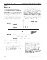
Travel
Travel
General
When the potentiometer voltage increases or
decreases from the neutral deadband, the
manager sends a travel request for
direction
or
and
speed (TRAVEL REQ) to the traction power
amplifier. The voltage from the
manager is directly related to the speed request.
As the input request changes, the travel request
voltage to the traction power amplifier mirrors
the change.
When a change in direction is requested, the
manager changes the direction
request to the traction power amplifier and
changes the speed request output (TRAVEL
REQ) to reflect the requested plugging strength.
Movin
Contro
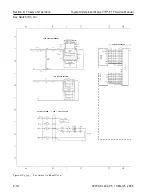
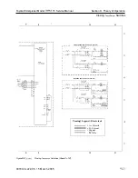
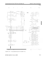
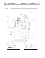
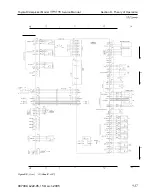
See the schematic in Figure 9-5 on page 9-24.
(The electrical schematic legend is on page 9-2.)
N
OTE
:
The current flowing through the drive
motor armature and field windings are
controlled independently of each other
by the traction power amplifier.
1. When the throttle is moved to the forward
position (tractor-first)
,
the wiper in the
variable resistor (VR-1) is moved so that
the voltage output decreases. The carriage
manager, sensing this decrease in voltage,
sends a communication message over the
transmit line to the tractor manager. The
tractor manager interprets this a s a
request for travel in the forward direction
and causes the following to occur:
N
OTE
:
For clarity and simplification, only
circuits directly related to vehicle travel
will be traced on the remaining
operation of the travel system diagram.
All are with respect to
TP4 (B-).
2. The
line to the traction
power amplifier is activated (driven to
about
This is the input to the
traction power amplifier which will
determine the drive motor field polarity to
enable travel in the forward direction.
3.
The traction power amplifier will then drive
its internal field control transistors to t u r n
the drive motor in the correct direction.
4. Simultaneously a n analog voltage, which
represents and is proportional to the
throttle command, is outputted from the
steer tractor manager and sent to the
traction power amplifier. This voltage
(TRAVEL
ranges from to about
VDC depending on throttle input
WRT TRAVEL REF. Based on this, the TPA
will control the strength of the field and
armature to obtain the proper travel speed
in the appropriate amount of time. The
higher the voltage the faster the TPA will
make the truck travel.
N
OTE
:
Travel speed is limited until the operator
requests steering and the
manager detects the request.
5. The TRAVEL REQ voltage is used by the
traction power amplifier to drive the
armature and field transistors to meet the
throttle request. The armature transistor
is, in effect, connecting terminal M- to
(in varying amounts) allowing current to
flow through the drive motor armature.
The traction power amplifier will also drive
its internal field transistors which, in turn,
will control the amount and direction of
flow through the drive motor field winding.
When a plug is requested, the
manager changes the
direction request to the traction power
amplifier and changes the speed request
output (TRAVEL
to reflect the
requested plugging strength. Current now
flows from
through:
FU3
Drive motor armature
B-
To battery negative
6.
During operation, the traction power
amplifier monitors for:
Armature current*
9-2 2
00700-CL222-05, 1
5 March 2005
Содержание 7BPUE15
Страница 1: ...Serial Numbers Service Manual 80 001 and up 7BPUE15...
Страница 2: ......
Страница 5: ......
Страница 22: ...Toyota Orderpicker Model 7BPUE15 Service Manual Section 2 Safety Section 2 Safety 00700 CL222 05 15 March 2005...
Страница 58: ......
Страница 128: ...Toyota Orderpicker Model 7BPUE15 Service Manual Section 6 Codes and Tests Code 4 1 00700 CL222 05 15 March 2005...
Страница 144: ......
Страница 168: ...Toyota Orderpicker Model 7BPUE15 Service Manual Section 7 Component Procedures 00700 CL222 05 15 March 2005 7 24a...
Страница 169: ...Section 7 Component Procedures Toyota Orderpicker Model 7BPUE15 Service Manual 7 24b 00700 CL222 05 15 March 2005...
Страница 170: ...Toyota Orderpicker Model 7BPUE15 Service Manual Section 7 Component Procedures 00700 CL222 05 15 March 2005 7 24c...
Страница 171: ...Section 7 Component Procedures Toyota Orderpicker Model 7BPUE15 Service Manual 7 24d 00700 CL222 05 15 March 2005...
Страница 172: ...Toyota Orderpicker Model 7BPUE15 Service Manual Section 7 Component Procedures 00700 CL222 05 15 March 2005 7 24e...
Страница 173: ...Section 7 Component Procedures Toyota Orderpicker Model 7BPUE15 Service Manual 7 24f 00700 CL222 05 15 March 2005...
Страница 174: ...Toyota Orderpicker Model 7BPUE15 Service Manual Section 7 Component Procedures 00700 CL222 05 15 March 2005 7 24g...
Страница 175: ...Section 7 Component Procedures Toyota Orderpicker Model 7BPUE15 Service Manual 7 24h 00700 CL222 05 15 March 2005...
Страница 176: ...Toyota Orderpicker Model 7BPUE15 Service Manual Section 7 Component Procedures 00700 CL222 05 15 March 2005 7 24i...
Страница 177: ...Section 7 Component Procedures Toyota Orderpicker Model 7BPUE15 Service Manual 7 24j 00700 CL222 05 15 March 2005...
Страница 178: ...Toyota Orderpicker Model 7BPUE15 Service Manual Section 7 Component Procedures 00700 CL222 05 15 March 2005 7 24k...
Страница 179: ...Section 7 Component Procedures Toyota Orderpicker Model 7BPUE15 Service Manual 7 24l 00700 CL222 05 15 March 2005...
Страница 180: ...Toyota Orderpicker Model 7BPUE15 Service Manual Section 7 Component Procedures 00700 CL222 05 15 March 2005 7 24m...
Страница 181: ...Section 7 Component Procedures Toyota Orderpicker Model 7BPUE15 Service Manual 7 24n 00700 CL222 05 15 March 2005...
Страница 182: ...Toyota Orderpicker Model 7BPUE15 Service Manual Section 7 Component Procedures 00700 CL222 05 15 March 2005 7 24o...
Страница 183: ...Section 7 Component Procedures Toyota Orderpicker Model 7BPUE15 Service Manual 7 24p 00700 CL222 05 15 March 2005...
Страница 184: ...Toyota Orderpicker Model 7BPUE15 Service Manual Section 7 Component Procedures 00700 CL222 05 15 March 2005 7 24q...
Страница 185: ...Section 7 Component Procedures Toyota Orderpicker Model 7BPUE15 Service Manual 7 24r 00700 CL222 05 15 March 2005...
Страница 186: ...Toyota Orderpicker Model 7BPUE15 Service Manual Section 7 Component Procedures 00700 CL222 05 15 March 2005 7 24s...
Страница 299: ......
Страница 301: ......
Страница 346: ......
Страница 358: ......
Страница 374: ...Toyota Orderpicker Model 7BPUE15 Service Manual Section A Appendix Section A Appendix 00700 CL222 05 15 March 2005...
Страница 386: ...Figure A 6 Cont Elec Schematic Sheet I Part 2 of 2 00700 CL222 05 15 March 2005...
Страница 389: ......
Страница 391: ...Hydraulic Schematic RES Figure A 9 Hydraulic Schematic 00700 CL222 05 15 March 2005...
Страница 399: ...Index Toyota Orderpicker Model 7BPUE15 Service Manual This page intentionallyleft blank 00700 CL222 05 15 March 2005...
Страница 400: ......
Страница 401: ...Printed in the USA...


