


Toyota Orderpicker Model
15
Service Manual
Section
8.
Wire Guidance
Theory of Operation
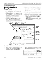
The steer controller compares the strength of
The HA and DFW settings may be changed in
four guidance signals
LL,
and
the Truck Configure Menu using
determines the truck's distance from wire
software. See "Options" on page 10-9.
and heading angle (HA). The steer
controller uses the
and HA to correct the
When the steer controller calculates the HA and
steering via the tractor steer manager.
DFW, it sends a steering correction request to
the
manager via the
(BUS+, BUS-). The
manager then
tells the steer power head which direction to
steer. This command causes the drive unit to
turn.
For example, if the steer controller calculates
that the truck is 1" to the right of the wire, it
The heading angle is the angle between the
tells the
manager to t u r n the drive
direction the truck is pointed and the guide
unit and move the truck toward the left until all
wire. The steer controller calculates the angle
4
guidance signals
LL, LR) are equal
by comparing the TL, TR, LL and LR signals.
distance from the wire.
For example, if the TL and LR signals are
stronger than the TR and LL signals, the truck
is pointed to the right of the guide wire. This
calculation is compared to the configured
settings of HA slow and HA stop. If HA slow is
and if the heading angle is greater than
travel speed is limited. If HA stop is
and
the heading angle is greater than
travel will
come to a controlled stop.
While the drive unit is turning, the steer
feedback encoder reports the amount the drive
unit is turning. This encoder is mounted
directly on the steer motor's armature shaft and
rotates with the steer motor. As the encoder
turns, it sends two voltages, CHA and CHB, to
the
manager. The
manager uses these voltages to track the drive
unit position, then sends the information to the
via the CAN bus. CHA and CHB
change state from approximately
5
volts to
volts and back a s the encoder rotates. The
resulting number of times the 2 channels
change state indicates how far the drive unit
h a s turned. When the required amount of
turning is sensed, the steer command is
removed.
Distance from wire
is the distance the
centerline of the truck is from the guide wire.
The steer controller calculates this distance by
comparing the TL, TR, LL and LL. For example,
if the TL and LR are stronger than the TR and
The steer controller also verifies the direction
the drive unit is turning. CHA changing state
before CHB indicates one direction. CHB
changing state before CHA indicates the
opposite direction.
LR signals, the left guidance coils are closer to
the guide wire than the right guidance coils.
wire, once a steer request is carried out and the
The factory default settings for DFW slow is
truck moves forward, the sensors' relationship
1.6". If this distance is greater than
travel
speed is limited. The factory default setting for
DFW stop is 3". If the distance is greater than
the travel will come to a controlled stop.
feedback encoder, until the truck is both
parallel to and directly over the wire.
1
5
March
2005
Содержание 7BPUE15
Страница 1: ...Serial Numbers Service Manual 80 001 and up 7BPUE15...
Страница 2: ......
Страница 5: ......
Страница 22: ...Toyota Orderpicker Model 7BPUE15 Service Manual Section 2 Safety Section 2 Safety 00700 CL222 05 15 March 2005...
Страница 58: ......
Страница 128: ...Toyota Orderpicker Model 7BPUE15 Service Manual Section 6 Codes and Tests Code 4 1 00700 CL222 05 15 March 2005...
Страница 144: ......
Страница 168: ...Toyota Orderpicker Model 7BPUE15 Service Manual Section 7 Component Procedures 00700 CL222 05 15 March 2005 7 24a...
Страница 169: ...Section 7 Component Procedures Toyota Orderpicker Model 7BPUE15 Service Manual 7 24b 00700 CL222 05 15 March 2005...
Страница 170: ...Toyota Orderpicker Model 7BPUE15 Service Manual Section 7 Component Procedures 00700 CL222 05 15 March 2005 7 24c...
Страница 171: ...Section 7 Component Procedures Toyota Orderpicker Model 7BPUE15 Service Manual 7 24d 00700 CL222 05 15 March 2005...
Страница 172: ...Toyota Orderpicker Model 7BPUE15 Service Manual Section 7 Component Procedures 00700 CL222 05 15 March 2005 7 24e...
Страница 173: ...Section 7 Component Procedures Toyota Orderpicker Model 7BPUE15 Service Manual 7 24f 00700 CL222 05 15 March 2005...
Страница 174: ...Toyota Orderpicker Model 7BPUE15 Service Manual Section 7 Component Procedures 00700 CL222 05 15 March 2005 7 24g...
Страница 175: ...Section 7 Component Procedures Toyota Orderpicker Model 7BPUE15 Service Manual 7 24h 00700 CL222 05 15 March 2005...
Страница 176: ...Toyota Orderpicker Model 7BPUE15 Service Manual Section 7 Component Procedures 00700 CL222 05 15 March 2005 7 24i...
Страница 177: ...Section 7 Component Procedures Toyota Orderpicker Model 7BPUE15 Service Manual 7 24j 00700 CL222 05 15 March 2005...
Страница 178: ...Toyota Orderpicker Model 7BPUE15 Service Manual Section 7 Component Procedures 00700 CL222 05 15 March 2005 7 24k...
Страница 179: ...Section 7 Component Procedures Toyota Orderpicker Model 7BPUE15 Service Manual 7 24l 00700 CL222 05 15 March 2005...
Страница 180: ...Toyota Orderpicker Model 7BPUE15 Service Manual Section 7 Component Procedures 00700 CL222 05 15 March 2005 7 24m...
Страница 181: ...Section 7 Component Procedures Toyota Orderpicker Model 7BPUE15 Service Manual 7 24n 00700 CL222 05 15 March 2005...
Страница 182: ...Toyota Orderpicker Model 7BPUE15 Service Manual Section 7 Component Procedures 00700 CL222 05 15 March 2005 7 24o...
Страница 183: ...Section 7 Component Procedures Toyota Orderpicker Model 7BPUE15 Service Manual 7 24p 00700 CL222 05 15 March 2005...
Страница 184: ...Toyota Orderpicker Model 7BPUE15 Service Manual Section 7 Component Procedures 00700 CL222 05 15 March 2005 7 24q...
Страница 185: ...Section 7 Component Procedures Toyota Orderpicker Model 7BPUE15 Service Manual 7 24r 00700 CL222 05 15 March 2005...
Страница 186: ...Toyota Orderpicker Model 7BPUE15 Service Manual Section 7 Component Procedures 00700 CL222 05 15 March 2005 7 24s...
Страница 299: ......
Страница 301: ......
Страница 346: ......
Страница 358: ......
Страница 374: ...Toyota Orderpicker Model 7BPUE15 Service Manual Section A Appendix Section A Appendix 00700 CL222 05 15 March 2005...
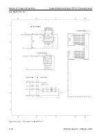
Страница 386: ...Figure A 6 Cont Elec Schematic Sheet I Part 2 of 2 00700 CL222 05 15 March 2005...
Страница 389: ......
Страница 391: ...Hydraulic Schematic RES Figure A 9 Hydraulic Schematic 00700 CL222 05 15 March 2005...
Страница 399: ...Index Toyota Orderpicker Model 7BPUE15 Service Manual This page intentionallyleft blank 00700 CL222 05 15 March 2005...
Страница 400: ......
Страница 401: ...Printed in the USA...


