


Toyota Orderpicker Model
15 Service Manual
Section 7 . Component Procedures
Mast Section
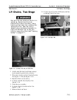
Mast Disassembly and Shimming
Mast Disassembly and
Shimming
This section describes procedures for:
Disassembling the three-stage mast
Shimming main frame to outer mast
Shimming outer mast to inner mast
Shimming inner mast to carriage
N
OTE
:
Two-stage masts require similar
procedures with the references to the
center lift cylinder and inner mast not
applying.
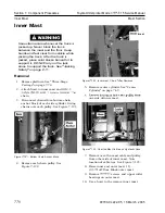
Mast Disassembly
1. Remove the forks and mast guard.
2.
Fully lower the carriage and make sure the
pressure is out of the cylinders.
3. Turn the key switch OFF and disconnect
the battery connector. Remove the battery.
4.
Disconnect the over-the-mast cables and
hoses inside the tractor compartment and
plug the hoses. Disconnect the lift hose to
the side cylinders inside the tractor
compartment and plug. Disconnect all
other cables that run from the tractor to
the mast.
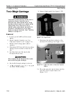
5. Secure the main carriage and masts so
they cannot move.
6. Remove the tractor from the mast and
block each securely.
7.
Disconnect and remove the lift chains
from the center lift cylinder. Remove the
over pulley cables and hoses. Remove the
center cylinder end cap assembly.
Mast assembly may swing free when
lowering. Use extreme caution.
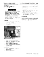
8.
With a suitable hoist, carefully lay the
mast assembly down and block securely in
place. Remove the carriage stops from the
inner mast.
9.
Remove the main carriage by sliding it out
the top of the inner mast. Set it aside for
later reassembly.
10. Disconnect and remove the lift cylinders
from the masts.
1 1. Attach the hoist to the inner mast.
12. Remove the upper roller bearing bosses
and roller bearings from the outer mast.
13. Remove the masts and mainframe stops.
Failure to properly balance load may
result in personal injury. Use extreme
caution.
14. Slide the inner mast out of the top of the
outer mast. Attach the hoist to the outer
mast.
15. Remove the upper roller bearing bosses
and roller bearings from the main frame.
Failure to properly balance load may
result in personal injury. Use extreme
caution.
16. Slide the outer mast out of the top of the
main frame.
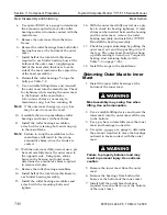
Shimming Main Frame to Outer
Mast
1. Install the mast roller bearings at the
bottom of the outer mast.
Mast assembly may swing free when
lifting. Use extreme caution.
2. Use a suitable lifting device and insert the
outer mast into the main frame all the way
to the bottom.
3. Using a pry bar, move the outer mast and
roller bearing to one side.
00700-CL222-05, 1 5 March 2005
Содержание 7BPUE15
Страница 1: ...Serial Numbers Service Manual 80 001 and up 7BPUE15...
Страница 2: ......
Страница 5: ......
Страница 22: ...Toyota Orderpicker Model 7BPUE15 Service Manual Section 2 Safety Section 2 Safety 00700 CL222 05 15 March 2005...
Страница 58: ......
Страница 128: ...Toyota Orderpicker Model 7BPUE15 Service Manual Section 6 Codes and Tests Code 4 1 00700 CL222 05 15 March 2005...
Страница 144: ......
Страница 168: ...Toyota Orderpicker Model 7BPUE15 Service Manual Section 7 Component Procedures 00700 CL222 05 15 March 2005 7 24a...
Страница 169: ...Section 7 Component Procedures Toyota Orderpicker Model 7BPUE15 Service Manual 7 24b 00700 CL222 05 15 March 2005...
Страница 170: ...Toyota Orderpicker Model 7BPUE15 Service Manual Section 7 Component Procedures 00700 CL222 05 15 March 2005 7 24c...
Страница 171: ...Section 7 Component Procedures Toyota Orderpicker Model 7BPUE15 Service Manual 7 24d 00700 CL222 05 15 March 2005...
Страница 172: ...Toyota Orderpicker Model 7BPUE15 Service Manual Section 7 Component Procedures 00700 CL222 05 15 March 2005 7 24e...
Страница 173: ...Section 7 Component Procedures Toyota Orderpicker Model 7BPUE15 Service Manual 7 24f 00700 CL222 05 15 March 2005...
Страница 174: ...Toyota Orderpicker Model 7BPUE15 Service Manual Section 7 Component Procedures 00700 CL222 05 15 March 2005 7 24g...
Страница 175: ...Section 7 Component Procedures Toyota Orderpicker Model 7BPUE15 Service Manual 7 24h 00700 CL222 05 15 March 2005...
Страница 176: ...Toyota Orderpicker Model 7BPUE15 Service Manual Section 7 Component Procedures 00700 CL222 05 15 March 2005 7 24i...
Страница 177: ...Section 7 Component Procedures Toyota Orderpicker Model 7BPUE15 Service Manual 7 24j 00700 CL222 05 15 March 2005...
Страница 178: ...Toyota Orderpicker Model 7BPUE15 Service Manual Section 7 Component Procedures 00700 CL222 05 15 March 2005 7 24k...
Страница 179: ...Section 7 Component Procedures Toyota Orderpicker Model 7BPUE15 Service Manual 7 24l 00700 CL222 05 15 March 2005...
Страница 180: ...Toyota Orderpicker Model 7BPUE15 Service Manual Section 7 Component Procedures 00700 CL222 05 15 March 2005 7 24m...
Страница 181: ...Section 7 Component Procedures Toyota Orderpicker Model 7BPUE15 Service Manual 7 24n 00700 CL222 05 15 March 2005...
Страница 182: ...Toyota Orderpicker Model 7BPUE15 Service Manual Section 7 Component Procedures 00700 CL222 05 15 March 2005 7 24o...
Страница 183: ...Section 7 Component Procedures Toyota Orderpicker Model 7BPUE15 Service Manual 7 24p 00700 CL222 05 15 March 2005...
Страница 184: ...Toyota Orderpicker Model 7BPUE15 Service Manual Section 7 Component Procedures 00700 CL222 05 15 March 2005 7 24q...
Страница 185: ...Section 7 Component Procedures Toyota Orderpicker Model 7BPUE15 Service Manual 7 24r 00700 CL222 05 15 March 2005...
Страница 186: ...Toyota Orderpicker Model 7BPUE15 Service Manual Section 7 Component Procedures 00700 CL222 05 15 March 2005 7 24s...
Страница 299: ......
Страница 301: ......
Страница 346: ......
Страница 358: ......
Страница 374: ...Toyota Orderpicker Model 7BPUE15 Service Manual Section A Appendix Section A Appendix 00700 CL222 05 15 March 2005...
Страница 386: ...Figure A 6 Cont Elec Schematic Sheet I Part 2 of 2 00700 CL222 05 15 March 2005...
Страница 389: ......
Страница 391: ...Hydraulic Schematic RES Figure A 9 Hydraulic Schematic 00700 CL222 05 15 March 2005...
Страница 399: ...Index Toyota Orderpicker Model 7BPUE15 Service Manual This page intentionallyleft blank 00700 CL222 05 15 March 2005...
Страница 400: ......
Страница 401: ...Printed in the USA...


