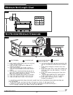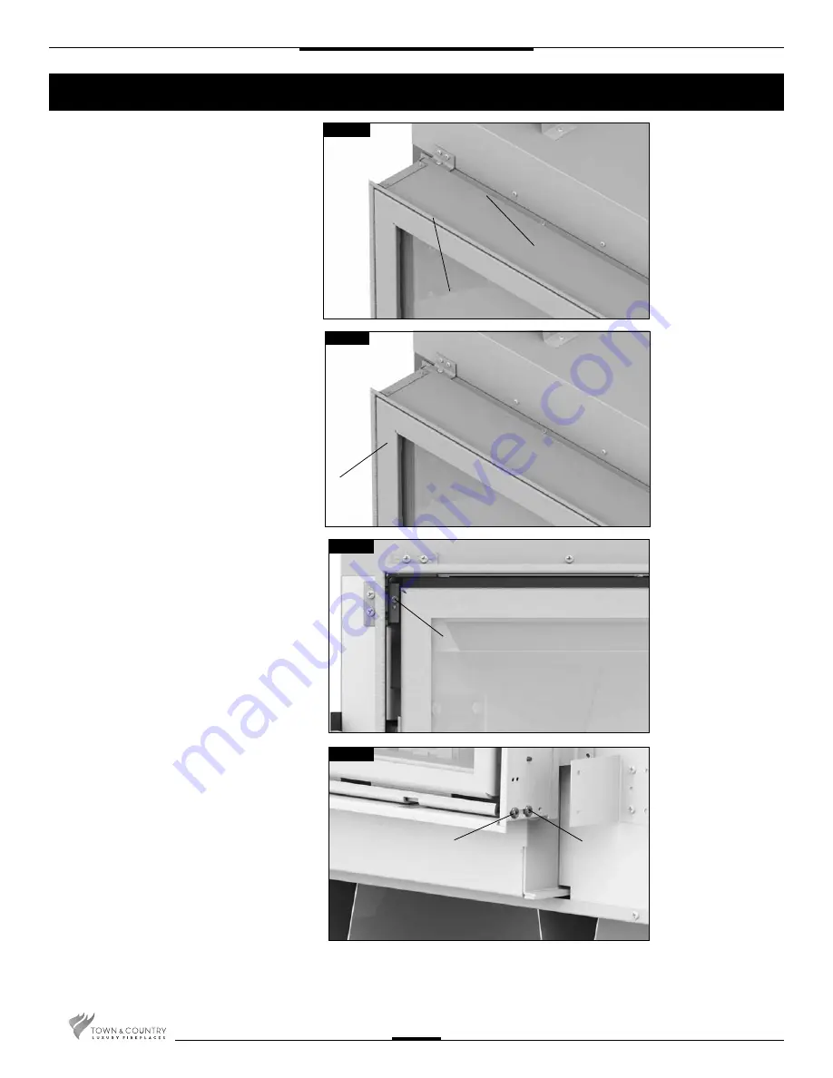
Adjustable Lintel
Fig. #16
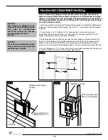
Fig. #17
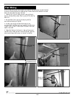
Fig. #18
1. The adjustable lintel assembly has two
orientations for desired fi nishing. The fl anged
edge and the hemmed edge. The lintel
comes factory installed with the fl ange edge
out . If the desired edge is different from the
factory setting, use the following steps to
change it(Fig.#16).
2. Remove the window trim from the window
frame (Fig.#17).
3. Pull the lintel assembly away from the fi re-
place to disengage from the lintel support
brackets.
4. Rotate the assembly to have the desired
edge away from the fi replace then align and
re-engage on the lintel support brackets .
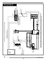
5. Remove the front bottom lintel screw located
on the bottom outside corners of the lintel
assembly and move it to the hole on the
other side of the center bottom lintel screw.
(Fig. #19).
NOTE: The lintel assembly has a maximum
range of adjustability of 5/8” to accommo-
date varying facing material thicknesses.
The maximum depth of facing material is
6” (Fig.#15b).
6. Slide the lintel in or out to desired position
within the maximum adjustable range.
7. Tighten the lintel clamping screws and the
bottom lintel screws. (Fig.#18).
8. Re-attach the window trim.
HEMMED EDGE
FLANGED EDGE
TRIM
LINTEL
CLAMPING
SCREW
Fig. #19
FRONT BOTTOM
LINTEL SCREW
CENTER
BOTTOM
LINTEL SCREW
14
TCWS.54CSTE 110712-72
Содержание TCWS54ST SERIES D
Страница 70: ...70 TCWS 54CSTE 110712 72 ...

