M
K
I
A
V
G
G
H
A
J
V
G
A
B
C
A
V
V
A
V
B
F
B
L
V
E
V
V
V
D
B
B
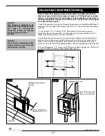
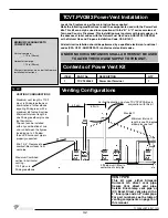
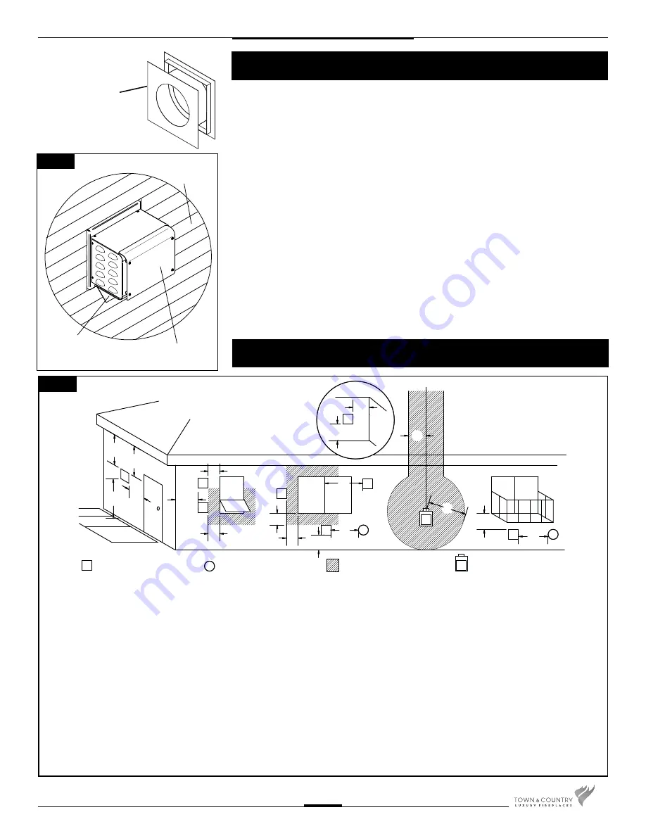
Wall Thimble
(Not Supplied)
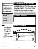
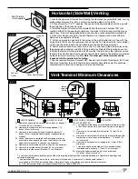
1. Locate the power vent termination following the clearance to combustible table, venting
confi guration diagram (Fig. #51), and terminal location diagram (Fig. #28).
2. Cut and frame an 11” x 11” opening. The centre of the square hole should line up with
the centre line of the horizontal pipe.
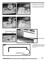
3. Install the Simpson Duravent (or equivalent) Wall thimble, part number 1247 (not
supplied with kit) in the opening to retain any insulation in the wall and maintain proper
clearances. If the wall being penetrated is constructed of noncombustible material only
(i.e.. Masonry block or concrete) the wall thimble is not required and a hole with zero
clearance is acceptable. (8” hole)
4. Drill an appropriate sized hole in the corner of the wall thimble that is in line with the
wiring hole in the back of the power vent and bring the 14-2 electrical wire (not supplied)
up through the holes in both the wall thimble and the back of the power vent.
5. Remove the Junction Box cover and join the 14-2 wire lead to the blower wires using
the appropriate connectors and attach the ground wire. Reinstall the junction box cover.
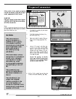
6. Attach the terminal to the outside wall. Ensure that the terminal is the right way up and
that only the outer fl anges that are used to secure the terminal to the building are covered
by the exterior wall or siding. (Fig.#52)
Note: No other part of the terminal can be
recessed into the exterior wall or siding.
7. Run the required Simpson Duravent GS / Secure Vent / Selkirk Direct-temp/ ICC Excel
Direct vent pipe from the unit to the terminal assembly. Assemble as per the vent pipe
manufacturer’s instructions including all shields and fi restops.
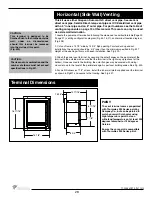
Horizontal (Side Wall) Venting
Exhaust
Outlet
Finished
Wall
Power Vent Terminal
Fig. #52
Fig. #2
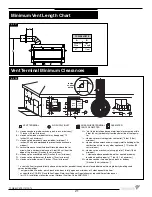
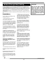
A= clearances above grade, veranda, porch, deck, or balcony [*
12 inches (30 cm) minimum]
B= clearance to window or door that may be opened [* 12
inches (30 cm) minimum]
C= clearance to permanently closed window [minimum 12
inches (30 cm) recommended to prevent condensation on
window]
D= vertical clearance to ventilated soffit located above the ter-
minal within a horizontal distance of 2 feet (60 cm) from the
edge of the terminal [12 inches (30 cm) minimum]
E= clearance to unventilated soffit [12 inches (30 cm) minimum]
F= clearance to outside corner [6 inches (15 cm) minimum]
G= clearance to inside corner [6 inches (15 cm) minimum]
H= * not to be installed above a meter/regulator assembly within
3 feet (90 cm) horizontally from the center-line of the regula-
tor
I= clearance to service regulator vent outlet [* 6 feet (1.8 m)
minimum]
J= clearance to nonmechanical air supply inlet to building or the
combustion air inlet to any other appliance [* 12 inches (30
cm) minimum]
K= clearance to a mechanical air supply inlet [* 6 feet (1.8 m)
minimum]
L= ^ clearance above paved side-walk or a paved driveway
located on public property [* 7 feet (2.1 m) minimum]
M= clearance under veranda, porch, deck, or balcony
[12 inches (30 cm) minimum**]
^ a vent shall not terminate directly above a side-walk or paved driveway which is located between two single family dwellings and
serves both dwellings*
** only permitted if veranda, porch, deck, or balcony is fully open on a minimum of 2 sides beneath the fl oor*
* as specifi ed in CGA B149 Installation Codes, Note: local Codes or Regulation may require different clearances
* for U.S.A. Installations follow the current National Fuel Gas Code, ANSI Z223.1
AIR SUPPLY INLET
VENT TERMINAL
GAS METER
FIXED
CLOSED
FIXED
CLOSED
OPEN-
ABLE
OPEN-
ABLE
INSIDE
CORNER
DETAIL
AREA WHERE TERMINAL
IS NOT PERMITTED
Vent Terminal Minimum Clearances
33
TCWS.54CSTE 110712-72
Содержание TCWS54ST SERIES D
Страница 70: ...70 TCWS 54CSTE 110712 72 ...


