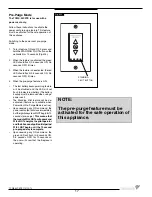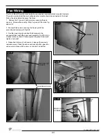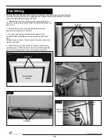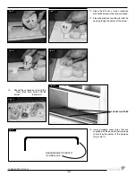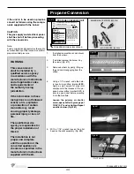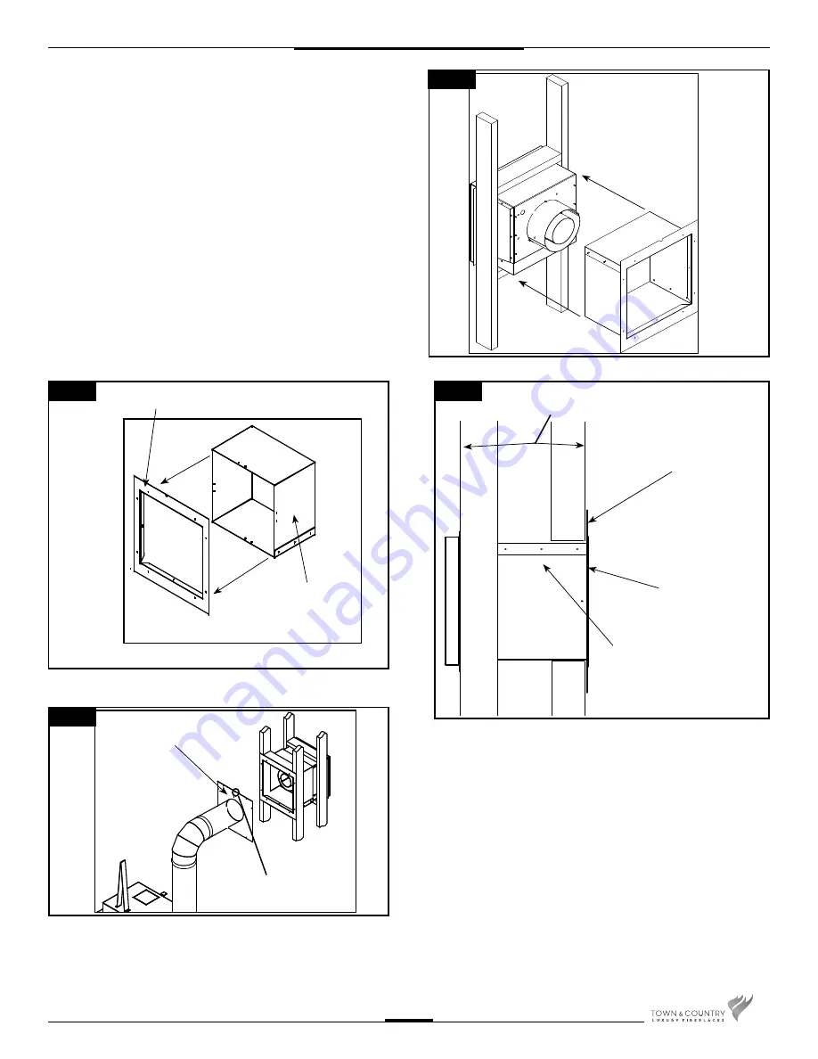
Fig. #42
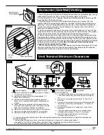
Fig. #43
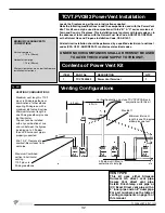
Fig. #45
INNER WALL PLATE
WALL SLEEVE
ASSEMBLY
WALL PIPE COVER
NOTCH AT TOP
Fig. #44
WALL THICKNESS GREATER THAN 7
1/2” UP TO MAX. 16 1/2”
INNER WALL PLATE
WALL SLEEVE
ASSEMBLY
WALL PIPE COVER
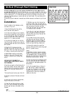
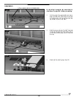
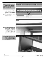
7. For wall thicknesses greater than 7 1/2” and up to a maximum of
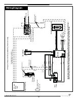
16 1/2”, attach the inner wall plate to the wall sleeve assembly, using
the four screws provided.(Fig #42) Then slide this assembly over the
terminal(Fig #43 & Fig. #44).
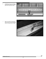
8. Slide the wall pipe cover, with the small notch oriented at the top,
over the vent pipe and attach pipe to the fi replace. (Fig #45) Connect
the vent pipe to the vent terminal and then secure the inner wall plate
and wall pipe cover to the framing. This ensures that any insulation is
retained in the wall and that the correct clearances are maintained.
NOTE: The vent terminal comes pre-painted, but can be painted to
match your wall fi nish colour using high temperature paint that can
withstand temperatures of at least 250 degrees Fahrenheit or 120
degrees Celcius.
9. Run the required Simpson Duravent GS / Secure Vent /
Selkirk Direct-temp or ICC Exceldirect pipe from the unit to the
terminal assembly. Assemble as per the vent pipe manufacturer’s
instructions including all shields and fi restops.
29
TCWS.54CSTE 110712-72
Содержание TCWS54ST SERIES D
Страница 70: ...70 TCWS 54CSTE 110712 72 ...


