22
Set the Control Throws
❏
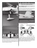
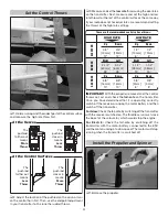
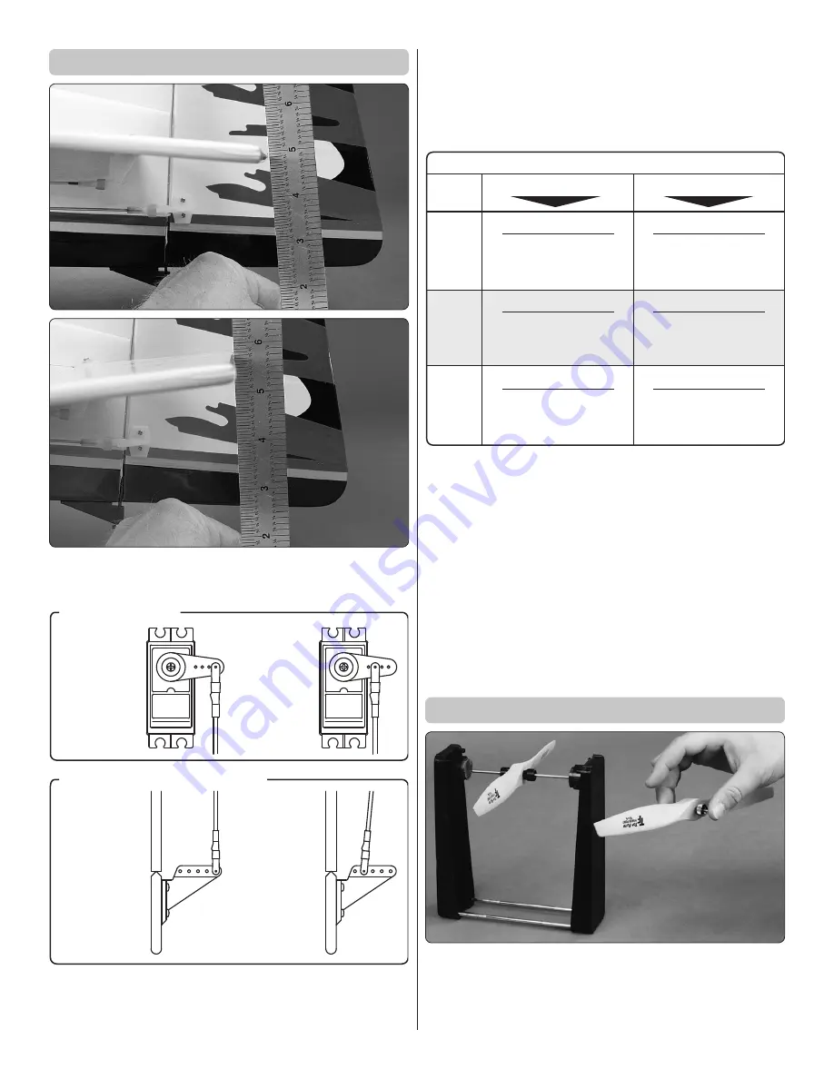
1. Hold a ruler against the widest part of the control surface
and measure the high rate throw fi rst.
The
pushrod
farther out
means
Less
Throw
The
pushrod
closer in
means
More
Throw
The
pushrod
farther out
means
More
Throw
The
pushrod
closer in
means
Less
Throw
At the Servos
At the Control Surfaces
❏
2. Adjust the location of the pushrod on the servo arm or
on the control horn fi rst. Then, use the endpoint adjustment
in your transmitter to fi ne tune the rudder throws.
❏
3. Measure and set the
low rate
throws using the dual rates
on the transmitter. Next, measure and set the high and low
rate throws for the rest of the control surfaces the same way.
If your radio does not have dual rates, we recommend setting
the throws at the high rate settings.
These are the recommended control surface throws:
E
LEV
A
T
O
R
HIGH RATE
LOW RATE
3/4"
[19 mm]
12°
Up
3/4"
[19 mm]
12°
Down
1/2"
[13 mm]
8°
Up
1/2"
[13 mm]
8°
Down
5/8"
[16 mm]
13°
Up
5/8"
[16 mm]
13°
Down
3/8"
[ 9 mm]
8°
Up
3/8"
[ 9 mm]
8°
Down
2-1/2"
[63 mm]
26°
Right
2-1/2"
[63 mm]
26°
Left
1-1/2"
[ 38 mm]
15°
Right
1-1/2"
[ 38 mm]
15°
Left
RUDDER
A
IL
ERON
S
IMPORTANT:
With the propeller removed and the control
throws set, set and check the
fail-safe
on the transmitter.
Once you have determined that it is operating correctly,
switch off the receiver or unplug the motor battery and then
switch off the transmitter.
For Glow:
Check the fail-safe by switching off the transmitter
with the receiver switched on. The throttle servo must close
the barrel of the carburetor, which would stop the engine.
For Electric:
Check the fail-safe by switching off the
transmitter with the motor battery connected to the ESC
and the motor running at a slow speed. The motor must stop
running when the transmitter is switched off.
Install the Propeller and Spinner
❏
1. Balance the propeller.

