background image

13

Install the Elevator Servo

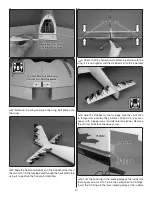
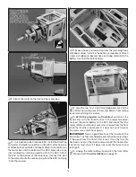
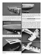
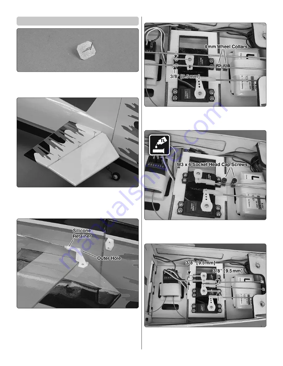
 1. Insert a T-pin into the center of six CA hinges.

 2. Insert the hinges into the trailing edge of the horizontal 

stabilizer, up to the T-pin.

 3. Test fi t the elevators to the horizontal stabilizer.

 4. Remove the T-pins and apply 6 drops of thin CA to 

both  sides  of  each  CA  hinge.  Test  pull  the  elevators  and 
add CA if needed.

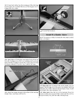
 5. Install the elevator control horns following the same 

procedure used to install the rudder control horn.

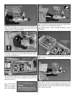
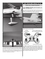
Elevator Servo Decision

: The elevators can be controlled 

by two elevator servos plugged into separate channels on 
the receiver or by one servo with the two elevator servo 
pushrods connected with two wheel collars.

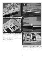
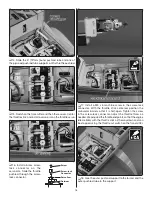
Single Elevator Servo

 1. Install the elevator servo. Harden the servo mount screw 

holes. Install the two 4mm wheel collars. Bend and cut the 
pushrods to fi t.

 2. Tighten the M3 x 6 socket head cap screws on the 

pushrods.

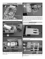
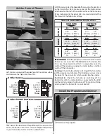
Two Elevator Servos

 1. Install the two elevator servos. Harden the servo 

mounting screw holes. Cut pushrods to length and use nylon 
Faslink the same way as the rudder and ailerons.

Содержание EDGE 540

Страница 1: ...age to the product personal property and cause serious injury This is a sophisticated hobby product It must be operated with caution and common sense and requires some basic mechanical ability Failure to operate this Product in a safe and responsible manner could result in injury or damage to the product or other property This product is not intended for use by children without direct adult superv...

Страница 2: ...ed correctly could possibly cause injury to yourself or spectators and damage to property 2 You must assemble the model according to the instructions Do not alter or modify the model as doing so may result in an unsafe or unflyable model In a few cases the instructions may differ slightly from the photos In those instances the written instructions should be considered as correct 3 You must take ti...

Страница 3: ...ncils or screwdrivers that may fall out of shirt or jacket pockets into the prop Stop the engine before making any engine adjustments The engine and muffler get hot Do not touch them during or right after operation Make sure fuel lines are in good condition so fuel will not leak onto a hot engine causing a fire To stop a glow powered engine set up a throttle cut on your transmitter to completely c...

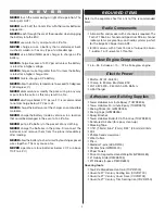
Страница 4: ...the plane immediately after landing NEVER allow the battery to short circuit by touching exposed wires together This may cause a fire NEVER operate or store batteries below 40 F or above 110 F 4 43 C REQUIRED ITEMS Refer to the separate sheet for a list of the recommended items Radio Components A transmitter and receiver with 4 channels is required The Tactic TTX660 6 channel and Spektrum DX6 6 ch...

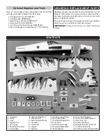
Страница 5: ...0 637 6050 If any parts are missing or damaged consult Tower Hobbies Order Assistance See phone numbers below IMPORTANT All parts are one per kit unless otherwise stated CONTENTS 1 Fuselage 2 Hatch 3 Cowl 4 Right Wing 5 Left Wing 6 Stabilizer Elevators 7 Fin Rudder 8 Main Landing Gear 9 Wheel Pants 10 Nylon Engine Mount 11 Tail Gear 12 Tail Wheel 13 Hinges 14 Spinner 15 Hook Loop Straps 16 Wing Bo...

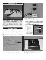
Страница 6: ...apply a couple drops of thin CA and check again 2 Follow the instruction included with your servos to install the rubber grommets and metal eyelets 3 Install a servo extension on the aileron servo 4 Center the aileron servo a Connect the servo to the receiver b Switch on the transmitter and temporarily connect the ESC and motor battery or a receiver battery to the receiver c Center the aileron tri...

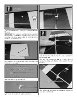
Страница 7: ...re install the screw 7 Route the aileron servo leads out of the holes in the bottom of the wing halves 8 Assemble the aileron pushrod 9 Attach the clevis to the nylon control horn 10 Position the control horn on the aileron and mark the two mounting holes 11 Drill 1 16 1 5mm pilot holes at the marks over the plywood mounting plate Do not drill completely through the wing 12 Mount the control horn ...

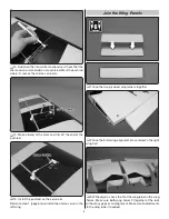
Страница 8: ...he pushrod on the servo arm Return to step 1 page 6 and install the aileron servo in the left wing Join the Wing Panels 1 Glue the two plywood wing joiners together 2 Glue the 3mm wing alignment pin centered in the right wing half 3 Without glue check the fit of the wing joiner in the wing halves Make sure both wing halves fit together at the root without any gaps or misalignment Make small adjust...

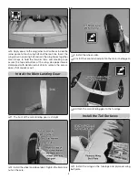
Страница 9: ...e wing Use paper towels dampened with denatured alcohol to remove the excess epoxy that squeezes out Install the Main Landing Gear 1 The front of the main landing gear is straight 2 Install the wheel and wheel pant Tighten the 5mm lock nut on the axle 3 Install the wheel collar 4 Install the second wheel pant on the main landing gear 5 Attach the main landing gear to the fuselage Install the Tail ...

Страница 10: ...arallel with the wing If it is not lightly sand the stabilizer slot until it is parallel 5 Glue the stabilizer in the fuselage Use the vertical fin to temporarily position the stabilizer Wipe off any excess epoxy with a paper towel and denatured alcohol Remove the vertical fin before the epoxy cures 6 Trim the covering in the leading edge of the rudder for the tail gear wire Insert a T pin in the ...

Страница 11: ...he tail gear bracket to the bottom of the fuselage Harden the screw holes with thin CA 10 Install the tail wheel Install the Rudder Servo Note The elevators will be installed after the rudder control horn is installed 1 Glow only We recommend the receiver battery tray be glued in the fuselage aft of the servo tray Before installing the battery tray make a hook and loop strap as shown Install the s...

Страница 12: ...p strap 5 Glow only Plug the receiver battery into the receiver switch and the receiver switch into the receiver Secure the connection between the receiver battery and receiver switch with tape or locking safety clips 6 Assemble and install the rudder pushrod and servo following the same method used for the aileron pushrod The screws to mount the rudder control horn pass completely through the rud...

Страница 13: ...ll the rudder control horn Elevator Servo Decision The elevators can be controlled by two elevator servos plugged into separate channels on the receiver or by one servo with the two elevator servo pushrods connected with two wheel collars Single Elevator Servo 1 Install the elevator servo Harden the servo mount screw holes Install the two 4mm wheel collars Bend and cut the pushrods to fit 2 Tighte...

Страница 14: ...o the front and back plates 4 Glue the four x 6mm x 20mm triangle sticks inside the motor box between the joints between the sides top and bottom 5 Remove the cooling air intake from the bottom of the firewall The easiest method is to drill 3 32 2 5mm holes at the six tabs 6 Use a 3 16 drill bit to drill the appropriate mounting holes for the motor box Refer to the sketch on page 16 and make sure ...

Страница 15: ...tery 12 Glue the two 10 x 10 x 60 mm hardwood sticks to the back of the firewall to prevent the motor battery from sliding forward and hitting the screws 13 With the propeller not installed switch on the transmitter with the throttle stick in the lowest position Connect the motor battery to the ESC and check that the motor rotates counterclockwise when viewed from the front when the throttle is ad...

Страница 16: ...s 2 Press the 6 32 blind nuts into the holes in the back of the firewall 3 Cut the spreader bar from both halves of the included nylon engine mount and trim off any remaining material so that they fit together well 4 Temporarily mount the engine mount on the firewall Do not tighten the screws completely 5 Test fit the engine on the engine mount Slide the mount halves together against the sides of ...

Страница 17: ...the threads in the plywood servo tray 9 Cut the outer throttle pushrod tubes and roughen them with sandpaper 10 Glue the short outer pushrod tube flush with the back of the firewall in the throttle pushrod hole 11 Bend the M2 x 500mm throttle pushrod as shown on page 27 12 Insert the throttle pushrod through the small outer pushrod tube 13 Slide a silicone clevis retainer on a nylon clevis Then th...

Страница 18: ...tor Screw Retainer Screw lock Connector Servo Arm 17 Install a M3 x 5 machine screw in the screw lock connector With the throttle stick centered position the carburetor barrel so that it is half open Tighten the screw in the screw lock connector Adjust the throttle throw as needed We adjusted the throttle endpoints so that the engine idles reliably with the throttle stick all the way down and can ...

Страница 19: ...arburetor Install the muffler and attach the fuel line with the plug pressure line to the muffler Insert the plug you just removed into the third fuel line This will be used as the fill line and routed out of the bottom of the cowl Install the Cowl For electric installation skip to step 2 1 Use a piece of paper or cardstock to make a template for the exhaust tubes 2 Make and attach templates to lo...

Страница 20: ...fler exhaust tubes or stock muffler Use the same method to trim access holes for the glow plug and the needle valve Route the fuel fill line with plug out of the bottom of the cowl Apply the Decals 1 Cut the decals from the decal sheet 2 Be certain the model is clean and free from oily fingerprints and dust Prepare a dishpan or small bucket with a mixture of liquid soap and warm water teaspoon of ...

Страница 21: ...mitter and then the receiver or connect the flight battery to the ESC Center the trims on the transmitter and the servo arms on the servos 2 Center the control surfaces FULL THROTTLE RUDDER MOVES RIGHT ELEVATOR MOVES DOWN RIGHT AILERON MOVES UP LEFT AILERON MOVES DOWN 3 Make certain that the control surfaces and carburetor or motor respond in the correct direction as shown in the diagram If any of...

Страница 22: ...ommended control surface throws ELEVATOR HIGH RATE LOW RATE 3 4 19mm 12 Up 3 4 19mm 12 Down 1 2 13mm 8 Up 1 2 13mm 8 Down 5 8 16 mm 13 Up 5 8 16 mm 13 Down 3 8 9 mm 8 Up 3 8 9 mm 8 Down 2 1 2 63mm 26 Right 2 1 2 63mm 26 Left 1 1 2 38mm 15 Right 1 1 2 38mm 15 Left RUDDER AILERONS IMPORTANT With the propeller removed and the control throws set set and check the fail safe on the transmitter Once you ...

Страница 23: ...on where it would be mounted inside until the model balances A good place to add stick on nose weight is to the firewall Do not attach weight to the cowl this will cause stress on the cowl and could cause it to crack at the screw holes Once you have determined if additional weight needs to be installed permanently attach the weight with glue or screws 4 IMPORTANT If you found it necessary to add a...

Страница 24: ...ssive free play in servo gears Insecure servo mounting and flying an over powered model at excessive speeds Takeoff If using a brushless motor it is a good idea to have a timer set on your transmitter wrist watch or cell phone We found that the plane can fly for 5 1 2 to 6 minutes or more on a 4S 3800mAh LiPo battery Set the timer for 5 minutes for the first few flights When recharging the battery...

Страница 25: ...ight rudder to counteract torque Climb out to make another attempt When the model is a foot or so off the deck smoothly increase up elevator until it gently touches down Once the model is on the runway and has lost flying speed hold up elevator to place the tail on the ground regaining tail wheel control FINAL NOTE Have a goal or flight plan in mind each time you fly This may be learning or improv...

Страница 26: ...e WARRANTY SERVICES Questions Assistance and Services Your local hobby store and or place of purchase cannot provide warranty sup port or service Once assembly setup or use of the Product has been started you must contact your local distributor or Horizon directly This will enable Horizon to better answer your questions and service you in the event that you may need any assistance For questions or...

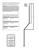
Страница 27: ... choice and at the sender s expense Horizon will hold non compliant Product for a period of 60 days from notification after which it will be discarded 10 2015 Country of Purchase United States of America Horizon Service Center 1608 Interstate Dr Champaign IL 61822 USA servicecenter horizonhobby com RequestForm REPAIRS REPAIR REQUESTS Horizon Product Support 1608 Interstate Dr Champaign IL 61822 US...

Страница 28: ...s Tactic and the Tower Hobbies logo are trademarks or registered trademarks of Horizon Hobby LLC The Spektrum trademark is used with permission of Bachmann Industries Inc All other trademarks service marks and logos are property of their respective owners ...

Отзывы: