


83
5
5
5
5.
.
.
.3
3
3
3.
.
.
.2
2
2
2
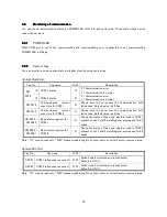
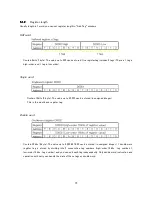
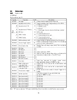
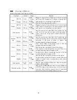
Other tags in PMIU unit
All these tags except input tags are writable.
Tag Type
Format
Range
Remarks
Bit/Coil
X xxxx
0000
- 3100
Input
Register
XW xxxx
00000
- 31015
Mapped to physical Input of Expansion I/O units. In digital
input, each bit corresponds to contacts. In analog input,
each register is corresponding to input channel.
Note that these tags cannot be written.
Bit/Coil
Y xxxx
0000
- 3100
Output
Register
YW xxxx
00000
- 31015
Mapped to physical Output of Expansion I/O units. In digital
output, each bit corresponds to contacts. In analog output,
each register is corresponding to output channel.
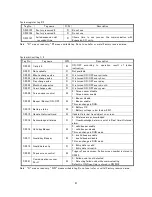
Data register
D xxxx
0000
- 4095
Used for store various data. Each bit of register tag can
used to bit/coil tag, but note that coil/bit addressed D
register cannot use as operand of contact instruction in
ladder block.
Bit/Coil
B xxxx
0000
- 4095
Internal
tag
Register
BW xxxx
0000
- 0255
Used for store various data. Each bit of register tag can
used to bit/coil tag, and can used as the operand of ladder
instruction.
If
the
value
is
written
in
register
tag,
corresponding bit/coil tags are changed.
Device
T
.
.
.
.
xxxx
0000
- 0255
Timer
device.
When
corresponding
timer
is
ON,
the
corresponding device changes to ON.
Note that period is put behind T about timer device.
Timer
Register
T xxxx
0000
- 4095
Timer register (current elapsed time is stored). If time is up,
corresponding timer device changes to ON.
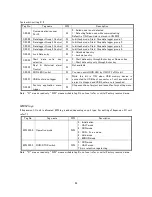
Device
C
.
.
.
.
xxxx
0000
- 0255
Counter device. When corresponding counter is ON, the
corresponding device changes to ON.
Note that period is put behind C about counter device.
Counter
Register
C xxxx
0000
- 4095
Counter register (current count value is stored). If the value
reaches
to
preset
value,
corresponding
counter
device
changes to ON.
Index register
I/J/K
xxxx
0000
Used for index modification. Refer
3.3.6. There is 3 registers
(I 0000, J 0000, K 0000).
Retentive register
R xxxx
0000
- 1399
Data register of EEPROM area. Even if power of PMIU unit
is OFF, the data in this memory area is not lost. Use to
store data that should be preserved even if unexpected
power failure occurs and writing frequency is low.
Содержание TR PMIU
Страница 11: ...1 Chapter Chapter Chapter Chapter 1 1 1 1 Introduction Introduction Introduction Introduction ...
Страница 15: ...5 Chapter 2 Chapter 2 Chapter 2 Chapter 2 Hardware Hardware Hardware Hardware ...
Страница 23: ...13 Input Wiring for TR PDIO0808 P Output ...
Страница 24: ...14 Wiring for TR PDIO0808 N Input Output ...
Страница 26: ...16 Input Input Wiring for TR PDIX1600 ...
Страница 28: ...18 Output Wiring for TRSDOX0016N ...
Страница 39: ...29 Chapter Chapter Chapter Chapter 3 3 3 3 TR PGMS TR PGMS TR PGMS TR PGMS ...
Страница 76: ...66 Chapter Chapter Chapter Chapter 4 4 4 4 Communication Communication Communication Communication ...
Страница 83: ...73 Chapter 5 Chapter 5 Chapter 5 Chapter 5 Tag Tag Tag Tag ...
Страница 98: ...88 Chapter Chapter Chapter Chapter 6 6 6 6 Task Task Task Task ...
Страница 119: ...109 Chapter Chapter Chapter Chapter 7 7 7 7 Expansion I O unit Expansion I O unit Expansion I O unit Expansion I O unit ...
Страница 124: ...114 Chapter 8 Chapter 8 Chapter 8 Chapter 8 Screen Screen Screen Screen ...
Страница 167: ...157 Note for the numbers of alarm message ...
Страница 176: ...166 Appendix Appendix Appendix Appendix ...
Страница 180: ...170 Append Append Append Append D D D D System System System System work flow work flow work flow work flow ...
Страница 181: ...171 ...
Страница 182: ...172 ...