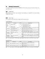


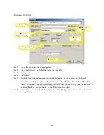
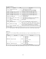


82
System bit/coil tag 2/2
Tag No.
Tag name
R/W
Description
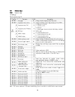
S 0022
Communication recover
Port 2
W
0 : Failed node is not detected
1 : Detecting failed node while communicating
Default is ON. Scan time is stored in SW 0019
S 0028
Data logger Group 1 Control
W
In bit task mode, Start/Stop data logger group 1.
S 0029
Data logger Group 2 Control
W
In bit task mode, Start/Stop data logger group 2.
S 0030
Data logger Group 3 Control
W
In bit task mode, Start/Stop data logger group 3.
S 0031
Data logger Group 4 Control
W
In bit task mode, Start/Stop data logger group 4.
S 0032
Lock Data entry
W
0 : Unlock data entry
1 : Lock data entry.
S 0033
Start
data
entry
key
selection
W
0 : Start data entry through Enter key or Numeric key
1 : Start data entry only through Enter key
S 0035
Real
&
Historical
alarm
Control
W
Not available
S 0036
RUN LED Control
W
You can control RUN LED by ON/OFF of this bit.
S 0037
USB host menu trigger
W
While
this
bit
is
ON,
when
USB
memory
device
is
connected to USB host connector of unit, execution of
project is stopped and USB host menu is launched.
S 0038
Factory
application
menu
trigger
W
Stop execution of project and launch factory setting menu.
Note : “R” means read only, “R/W” means writable tag. Do not use (refer or write) Factory reserved area.
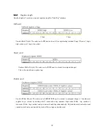
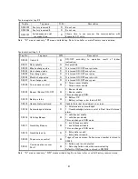
MW/M tags
If Expansion I/O unit is allocated, MW tag is added depending on unit type. For setting of Expansion I/O unit,
refer
7.1.
Note : “R” means read only, “R/W” means writable tag. Do not use (refer or write) Factory reserved area.
Tag No.
Tag name
R/W
Description
MW 0000
Operation mode
R/W
0 : Initialization
1 : HALT mode
2 : RUN mode
3 : RUN – Force mode.
4 : Hold mode
6 : ERROR mode
MW 0003
RUN/STOP switch
R/W
0 : RUN mode
1 : HALT mode.
This is retentive register tag.
Содержание TR PMIU
Страница 11: ...1 Chapter Chapter Chapter Chapter 1 1 1 1 Introduction Introduction Introduction Introduction ...
Страница 15: ...5 Chapter 2 Chapter 2 Chapter 2 Chapter 2 Hardware Hardware Hardware Hardware ...
Страница 23: ...13 Input Wiring for TR PDIO0808 P Output ...
Страница 24: ...14 Wiring for TR PDIO0808 N Input Output ...
Страница 26: ...16 Input Input Wiring for TR PDIX1600 ...
Страница 28: ...18 Output Wiring for TRSDOX0016N ...
Страница 39: ...29 Chapter Chapter Chapter Chapter 3 3 3 3 TR PGMS TR PGMS TR PGMS TR PGMS ...
Страница 76: ...66 Chapter Chapter Chapter Chapter 4 4 4 4 Communication Communication Communication Communication ...
Страница 83: ...73 Chapter 5 Chapter 5 Chapter 5 Chapter 5 Tag Tag Tag Tag ...
Страница 98: ...88 Chapter Chapter Chapter Chapter 6 6 6 6 Task Task Task Task ...
Страница 119: ...109 Chapter Chapter Chapter Chapter 7 7 7 7 Expansion I O unit Expansion I O unit Expansion I O unit Expansion I O unit ...
Страница 124: ...114 Chapter 8 Chapter 8 Chapter 8 Chapter 8 Screen Screen Screen Screen ...
Страница 167: ...157 Note for the numbers of alarm message ...
Страница 176: ...166 Appendix Appendix Appendix Appendix ...
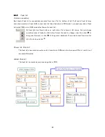
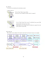
Страница 180: ...170 Append Append Append Append D D D D System System System System work flow work flow work flow work flow ...
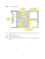
Страница 181: ...171 ...
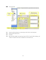
Страница 182: ...172 ...