


160
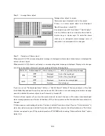
Step 4.
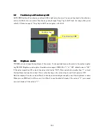
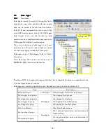
Arrange Alarm object
Arrange alarm object to screen.
Alarm message is displayed only to this object.
If there is no alarm object, alarm is not displayed.
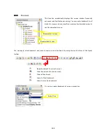
About Alarm object, refer
8.2.6.
In example shown left,” Ack Alarm”/”Ack All alarm”
is set as button object, you can also these task to
function keys or ladder logic. To make the alarm
state easy to distinguish, alarm message color of
each state is recommended to be changed.
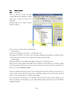
Step 5.
Operation of Alarm object
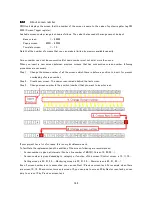
When alarm bit is ON, corresponding alarm message is displayed to alarm object. Latest alarm is displayed the
bottom of alarm object.
When alarm bit is ON, alarm is activated, so corresponding alarm message is displayed. Display color changes
according to the state of alarm bit and acknowledge bit. Refer following table.
If you are not set “Acknowledge Alarm” button or “Ack All Alarms” button of the screen object, or Key task
(both Global Key task and Screen Key task can be used for this), alarm is not acknowledged, and alarm message
cannot be deleted from alarm object (even if alarm bit is turned off).
If alarm is found, operator of your machine/system should be check the cause of the alarm. Unacknowledged
alarm message remains even if alarm bit had been OFF, so the operator can find the alarm that was activated in
the past.
If I take measures, acknowledge the alarm. So alarm is deleted from alarm object. If you set “historical alarm” in
alarm description, message is deleted from alarm object but history remains to battery backup area. The history
of alarm can upload to your PC by upload operation of TR PGMS with checking “Historical Alarm Data” option.
Refer
3.2.4.
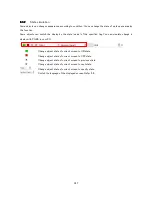
Alarm bit
Acknowledge bit
Alarm message is…
Color of corresponding message
OFF
Displayed
Active Acknowledged
ON
ON
Displayed
Active Un acknowledged
OFF
Displayed
In active Un acknowledged
OFF
ON
Deleted
Not displayed
Содержание TR PMIU
Страница 11: ...1 Chapter Chapter Chapter Chapter 1 1 1 1 Introduction Introduction Introduction Introduction ...
Страница 15: ...5 Chapter 2 Chapter 2 Chapter 2 Chapter 2 Hardware Hardware Hardware Hardware ...
Страница 23: ...13 Input Wiring for TR PDIO0808 P Output ...
Страница 24: ...14 Wiring for TR PDIO0808 N Input Output ...
Страница 26: ...16 Input Input Wiring for TR PDIX1600 ...
Страница 28: ...18 Output Wiring for TRSDOX0016N ...
Страница 39: ...29 Chapter Chapter Chapter Chapter 3 3 3 3 TR PGMS TR PGMS TR PGMS TR PGMS ...
Страница 76: ...66 Chapter Chapter Chapter Chapter 4 4 4 4 Communication Communication Communication Communication ...
Страница 83: ...73 Chapter 5 Chapter 5 Chapter 5 Chapter 5 Tag Tag Tag Tag ...
Страница 98: ...88 Chapter Chapter Chapter Chapter 6 6 6 6 Task Task Task Task ...
Страница 119: ...109 Chapter Chapter Chapter Chapter 7 7 7 7 Expansion I O unit Expansion I O unit Expansion I O unit Expansion I O unit ...
Страница 124: ...114 Chapter 8 Chapter 8 Chapter 8 Chapter 8 Screen Screen Screen Screen ...
Страница 167: ...157 Note for the numbers of alarm message ...
Страница 176: ...166 Appendix Appendix Appendix Appendix ...
Страница 180: ...170 Append Append Append Append D D D D System System System System work flow work flow work flow work flow ...
Страница 181: ...171 ...
Страница 182: ...172 ...