TOSHIBA
TMPR3904F Rev. 2.0
69
8.5.7
Page mode support and page hit detection
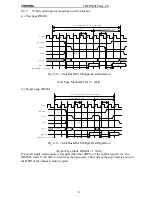
The page mode of the DRAM is a method to access while keeping asserting RAS* and changing
the column address under the fixed row address. In the DRAMC, when the bus master conducts
the burst mode access, the page mode of the DRAM is used. At the single word access, the page
mode access of the DRAM is not conducted. The DRAMC supports two modes--the fast page
mode and the hyper page mode (EDO). Selection of the fast page mode and hyper page mode is
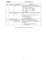
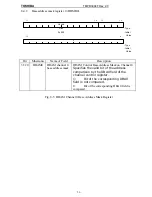
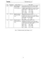
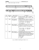
conducted in the DPMn (n=1,0) of the channel control register.
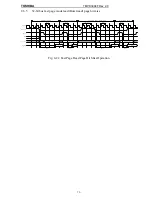
When the row address changes (at a page hit miss), the DRAMC negates the RAS*. The page
hit miss is caused when the row address changes and the page mode access still continues. After
the page hit miss, one access cycle of the normal mode is executed and the page mode access is
continued.
8.5.8
Column address counter
A 12-bit column address counter is used for the fast page mode and the hyper page mode. When
the page mode access continues beyond the number of the column words that is set up in the
DCWn (n=0,1) of the channel control register, a page hit miss occurs. Users cannot access this
column address counter.
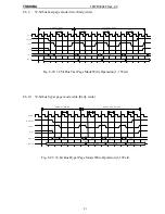
When the bus master conducts the burst mode access, the column address counter increments
address like as 0-4-8-C-10-... if the lower four-bit of burst starting address is 0x0. On the other
hand, it decrements address like as C-8-4-0-... if the starting address is 0xC.
8.5.9
Timing control
The timing control controls the switch timing of the row/column addresses and the timing of
RAS*/CAS* and WE*.
8.5.10
Refresh timing
The refresh supports the CAS before RAS refresh (CBR) and the CAS before RAS self refresh
(CBRS).
Normally, the CBR refresh is conducted. When a DRAM with the self refresh function is used
and the self refresh enable CBRSE of the refresh control register DREFC is 1, a self refresh is
conducted in the first refresh cycle after the TX3904 entered into the halt mode, and the refresh
timer is halted. When the halt mode is resolved, it recovers from the self refresh to the CBR
refresh. Please note that the contents of the DRAM are not retained when having shifted into the
self refresh mode using a DRAM without the self refresh function.
The refresh is conducted for Channel 0 and Channel 1 simultaneously. The refresh timer is 10
bits and programmable. Designate the number of clocks of the internal system clock with a
binary value for desired refresh cycle. For example, when the internal system clock is 50 MHz
(20 ns cycles), 15.6
µ
sec is 780 clocks so that the set-up should be (1100001100)
2
. The default
is (1100000000)
2
for 768 clocks (when @50 MHz) at 15.36
µ
sec. When using at a frequency
other than 50 MHz, the user is required to set up the appropriate number of cycles, taking the
DRAM access and refresh arbitration into consideration.
Содержание TMPR3904F
Страница 1: ...Users Manual 32bit RISC Microprocessor TX39 family TMPR3904F Rev 2 0 Jan 12 1998 ...
Страница 2: ......
Страница 9: ...Users Manual 01 1 INTRODUCTION 1 1 Overview ...
Страница 10: ...Users Manual 02 1 2 Notation used in this manual Mathematical notation Data notation Signal notation ...
Страница 11: ...Users Manual 03 1 3 Kind of accessing by the TX3904 ...
Страница 12: ...Users Manual 04 1 4 Precautions in the TMPR3904F specification Don t set Don t use ...
Страница 13: ...Users Manual 05 Do not use ...
Страница 14: ...Users Manual 06 ...
Страница 15: ...Users Manual 7 2 FEATURES n n n n n n n n n n n n n ...
Страница 16: ...Users Manual 8 ...
Страница 18: ...Users Manual 10 ...
Страница 19: ...Users Manual 11 4 PINS 4 1 Positions of Pins ...
Страница 20: ...Users Manual 12 ...
Страница 21: ...Users Manual 13 4 2 Functions of Pins ...
Страница 22: ...Users Manual 14 ...
Страница 23: ...Users Manual 15 ...
Страница 24: ...Users Manual 16 ...
Страница 26: ...Users Manual 18 5 2 Register Map ...
Страница 27: ...Users Manual 19 ...
Страница 28: ...Users Manual 20 ...
Страница 30: ...Users Manual 22 5 3 2 PIO2 and PIO1 ...
Страница 32: ...Users Manual 24 5 3 4 Connection of external bus master 5 3 5 INT 7 0 active status clear ...
Страница 33: ...Users Manual 25 5 3 6 INT 7 0 active status set up ...
Страница 34: ...Users Manual 26 ...
Страница 123: ...TOSHIBA TMPR3904F Rev 2 0 115 26 ...
Страница 169: ...TOSHIBA TMPR3904F Rev 2 0 161 26 ...
Страница 203: ...TOSHIBA TMPR3904F Rev 2 0 195 ...
Страница 230: ......

