TOSHIBA
TMPR3904F Rev. 2.0
144
26
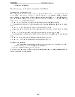
Dual address mode
The dual address mode is a mode that executes the transfer by the following two bus operations:
A read operation to output the address of the source device and to read the data from the
source device to take them in to the register (DHR) inside the DMAC.
A write operation to output the address of the destination device and to write the data of the
DHR to the destination device.
In the dual address mode, the following three kinds of transfers are possible:
Memory
→
Memory
Memory
→
I/O device
I/O device
→
Memory
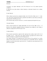
The data transfer unit of the DMAC is the data amount that was designated in the TrSiz field of
the CCRn (32 or 16 bits). In the external transfer request, the data of the amount of the transfer
unit are transferred every time a transfer request is acknowledged. It is always a word (4 bytes,
32 bits) for the transfer of the internal transfer request.
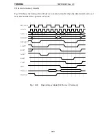
In the dual address mode, the data of the amount of the data transfer unit are read in to the DHR
from the source device, and then the data are written in to the destination device.
A memory access occurs according to the data transfer unit. However, two 16-bit memory
accesses occur when the data transfer unit is 32 bits and 16-bit width memory is designated by
memory controller.
Separated from the data transfer unit, the bus width (the device port size) of the I/O device is
designated in the DPS field of the CCRn for the data transfer from a memory to an I/O or from
an I/O to a memory. The device port size is 32, 16, or 8 bits.
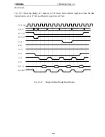
When the data transfer unit and the device port size are the same, the DMAC conducts one read
operation or write operation to the I/O device. The bus operation to a memory is always one
time; so, in this case, one transfer completes with two bus operations.
When the device port size is smaller than the data transfer unit, the DMAC conducts multiple
read operations or write operations to the I/O device. For example, to transfer data from an I/O
device whose data transfer unit is 32 bits and whose device post size is 8 bits to a memory, 8-bit
data are read out from the I/O device four times to be stored in the DHR; then the 32-bit data are
written in to the memory at one time (twice for 16-bit width memory).
The address and the value of BCRn are changed with the data transfer unit.
The set-up where the device port size is larger than the data transfer unit is inhibited.
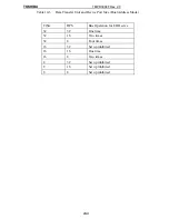
The following table shows the summary:
Содержание TMPR3904F
Страница 1: ...Users Manual 32bit RISC Microprocessor TX39 family TMPR3904F Rev 2 0 Jan 12 1998 ...
Страница 2: ......
Страница 9: ...Users Manual 01 1 INTRODUCTION 1 1 Overview ...
Страница 10: ...Users Manual 02 1 2 Notation used in this manual Mathematical notation Data notation Signal notation ...
Страница 11: ...Users Manual 03 1 3 Kind of accessing by the TX3904 ...
Страница 12: ...Users Manual 04 1 4 Precautions in the TMPR3904F specification Don t set Don t use ...
Страница 13: ...Users Manual 05 Do not use ...
Страница 14: ...Users Manual 06 ...
Страница 15: ...Users Manual 7 2 FEATURES n n n n n n n n n n n n n ...
Страница 16: ...Users Manual 8 ...
Страница 18: ...Users Manual 10 ...
Страница 19: ...Users Manual 11 4 PINS 4 1 Positions of Pins ...
Страница 20: ...Users Manual 12 ...
Страница 21: ...Users Manual 13 4 2 Functions of Pins ...
Страница 22: ...Users Manual 14 ...
Страница 23: ...Users Manual 15 ...
Страница 24: ...Users Manual 16 ...
Страница 26: ...Users Manual 18 5 2 Register Map ...
Страница 27: ...Users Manual 19 ...
Страница 28: ...Users Manual 20 ...
Страница 30: ...Users Manual 22 5 3 2 PIO2 and PIO1 ...
Страница 32: ...Users Manual 24 5 3 4 Connection of external bus master 5 3 5 INT 7 0 active status clear ...
Страница 33: ...Users Manual 25 5 3 6 INT 7 0 active status set up ...
Страница 34: ...Users Manual 26 ...
Страница 123: ...TOSHIBA TMPR3904F Rev 2 0 115 26 ...
Страница 169: ...TOSHIBA TMPR3904F Rev 2 0 161 26 ...
Страница 203: ...TOSHIBA TMPR3904F Rev 2 0 195 ...
Страница 230: ......

