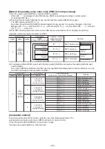
[Method of operating solenoid valve (forced ON)
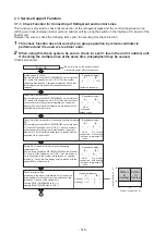
(1) Set the rotary switch [SW02] to 2, and five seconds later SV41 will come ON. [H.r 41] will be displayed in
the 7-segment display in the solenoid valve display screen.
(2) Any desired solenoid valve can be forced ON by changing the setting No. of the rotary switch [SW02].
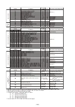
The following table shows the forced-ON/normal control patterns for each solenoid valve.
* The 7-segment display will show [H.r—] for outdoor unit models that do not have
solenoid
valves.
Rotary switch
7-segment display
(solenoid valve display)
Operation patterns of solenoid valve/heater
(
: Forced ON, – : normal control)
SW01
SW02
SW03
SV3F
SV3D
SV42
SV41
Compressor 1, 2
case heater
2
1
2
3
5
6
7 ~ 15
16
#
Used in
PMV
operations
–
–
–
–
–
–
–
–
–
–
–
–
–
–
–
–
–
–
–
[H.r – – –]
[H.r 4 1 ]
[H.r 4 2 ]
[H.r 3 F ]
[H.r 3 – ]
[H.r – – –]
[H.r A L L]
Function in O
u
tdoor Unit
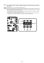
The solenoid valves provided to outdoor units can be forced ON (open) by switching operations at the interface
P.C. board of the outdoor unit.
Also, the
pulse motor
valves (PMV1, PMV2, PMV3, PMV4) of the outdoor unit can be forced to full-open,
half
open, and full-closed for two minutes.
Use this function to check for valve or PMV malfunctioning, clogging, and so forth.
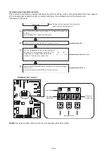
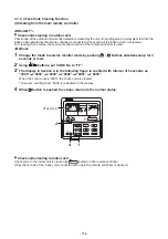
[Control start method]
(1)
Set the rotary switches [SW01/SW02/SW03] on the interface P.C. board of the outdoor unit to [2/1/3].
When [H.r ] is displayed, press the push switch [SW04] for one second or longer, which changes the
display to [H. r – – –], and this control is started.
long-press SW06
for 1 second
PMV display
[H. r – – –]
S
olenoid valve
display
[P.
∗
∗
∗
∗
]
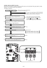
[Method to switch solenoid valve/PMV display]
(1)
Solenoid
valve display is made immediately after starting control.
The 7-segment display is [H. r – – –].
(2) Pressing the push switch [SW06] switches the display to [P.
],
which is PMV display.
Each time the push switch [SW06] is pressed, the display changes
between solenoid valve display and
pulse motor
valve (PMV)
display.
(3) Follow the method below for solenoid valve and PMV operations.
* Take care, as operations of each of the solenoid valve and PMV are
enabled, regardless of which is displayed.
SW04
SW01
Select PMV
Select solenoid valve
Start control /
PMV opening
switching
End control
Solenoid valve /
PMV display
switching
SW02
SW03
SW05
SW06
7-7-6.
Pulse Motor Valve (PMV) Forced Open/Close Function and Solenoid valve Forced ON
4
[H.r
3
D
]
–
–
–
- 159 -
Содержание MMY-MUP0801HT7JP
Страница 32: ...2 8 5 USB isolate P C board MCC 1754 USB communication to I F CN01 USB connector CN02 screw 32 ...
Страница 309: ......

