No.
Part
Work procedure
Remarks
Heat
exchanger
(continued)
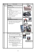
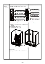
3) Cut the pipes at the heat exchanger (Fig.6, Fig.7).
3
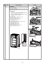
4) Remove the heat exchanger while draw it upward or at
rear side
<8 to 14HP (Fig.8)> : M5 × 10, 2 pcs
<
1
4A
to 24HP (Fig.9)> : M5 × 10, 8 pcs
2. Attachment
Carry out installation by following reverse procedure in the
detachment 1) to 4).
(1) Header pipe at the gas
side (Main heat exchanger)
(3) Header pipe at the gas
side (Sub-heat exchanger)
(2) Distributor at the liquid
side (Main heat exchanger)
(4) Distributor at the liquid
side (Sub-heat exchanger)
(1) Header pipe at the gas
side (Main heat exchanger)
(2) Distributor at the liquid
side (Main heat exchanger)
(3) Header pipe at the gas
side (Sub-heat exchanger)
(4) Distributor at the liquid
side (Sub-heat exchanger)
<8 to 14HP>
<
1
4A
to 24HP>
Fig. 6
Fig. 7
M5×10, 2 pcs
M5×10, 8 pcs
Fig. 8
Fig. 9
- 274 -
Содержание MMY-MUP0801HT7JP
Страница 32: ...2 8 5 USB isolate P C board MCC 1754 USB communication to I F CN01 USB connector CN02 screw 32 ...
Страница 309: ......

