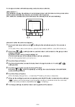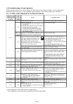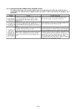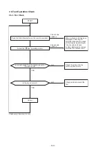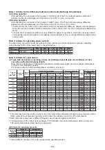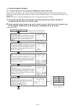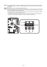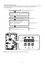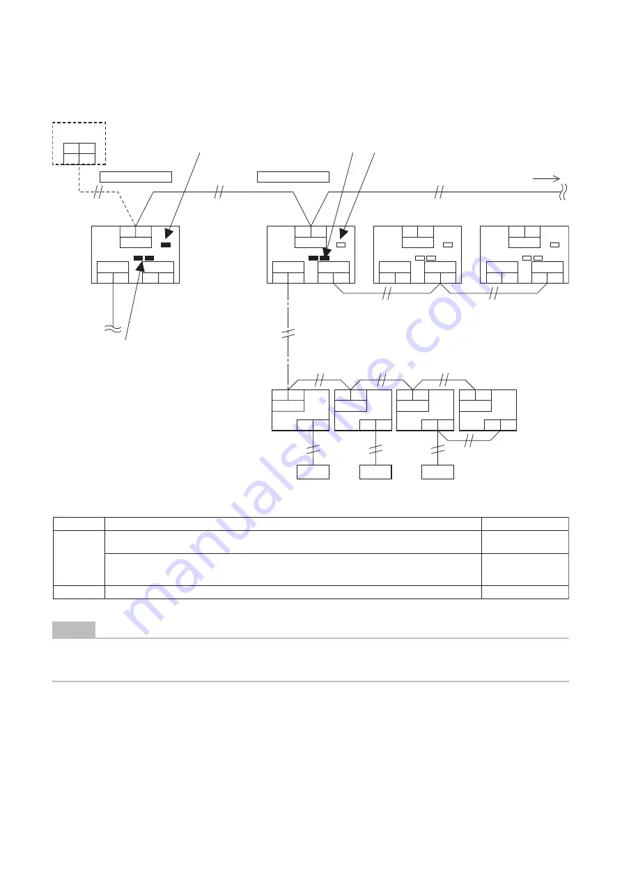
7-4-4. Check after Address Setup when Central Control System Is Connected
When the central control system is connected, check that the following setup has finished after address setup.
NOTE
The figure above does not show all the electric wires.
For details, refer to the installation manuals for the outdoor unit, indoor unit, remote controller, or optional
devices.
Central remote
controller
(1)
(3) (2)
(3)
Main check items
Check
U1 U2
Uv
A
B
U1 U2
Uv
A
B
U1 U2
Uv
A
B
U1 U2
Uv
A
B
U3 U4
U1 U2
Remote
controller
Remote
controller
Remote
controller
U3 U4
U1 U2
U5 U6
U3 U4
U1 U2
U5 U6
U3 U4
Line address = 1
Line address = 2
Other refrigerant line
Header unit (A)
Header unit (A)
Outdoor unit
Indoor unit
Follower unit (B)
Follower unit (C)
U1 U2
U5 U6
U3
To other refrigerant line
U4
U1 U2
U5 U6
(1) Is the terminator resistor (SW100-bit1) of the header unit with the smallest line address number in
the central control turned on? (Setup is unnecessary for follower units. (Factory default : OFF))
Terminator
resistor
Line address (3) Are addresses in the line address (SW101,SW102) not duplicated in each refrigerant line?
(2) Is the terminator resistor (SW100-bit1) of the header units, except for the line with the smallest
central control line address, turned off? (Setup is unnecessary for follower units.
(Factory default : OFF))
Uv
Uc
Uh
Uv
Uc
Uh
Uv
Uc
Uh
Uv
Uc
Uh
- 135 -
Содержание MMY-MUP0801HT7JP
Страница 32: ...2 8 5 USB isolate P C board MCC 1754 USB communication to I F CN01 USB connector CN02 screw 32 ...
Страница 309: ......


