7-3. Check at Main Power-on
After turning on the main power of the indoor units and outdoor unit in the refrigerant line to conduct a test
operation, check the following items in each outdoor and indoor unit.
(After turning on the main power, be sure to check in order: indoor unit outdoor unit.)
<Check on the outdoor unit>
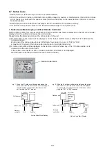
(1) Check that all the rotary switches, SW01, SW02, and SW03, on the interface PC board of the header unit
are set to “1.”
(2) If another check code is displayed on the 7-segment display [B], remove the cause of the problem referring
to Section, “8. TROUBLESHOOTING”.
(3) Check that “L08” is displayed on the 7-segment display [B] on the interface PC board of the header unit.
(L08: Indoor address not set up)
(If the address setup operation has already been completed during servicing, etc., the above check code is
not displayed, and only “U1” is displayed on the 7-segment display [A].)
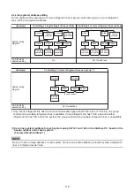
Interface P.C. board
%0
%0
%0
%0
%0
%0
10
10
10
10
10
10
+%
+%
59
59
59
2
10
0
%
0
%
0
%
(
(
%0
%0
%0
%0
%0
%0
%0
%0
%0
%0
%0
59
59
59
59
59
59
59
%0
.
.
%0
%0
%0
%0
59
59
59
%0
%0
7
7
7
7
7X
7J
7X
7J
7E
7E 5*+'.&
5*+'.&
5*+'.& 7
7 5*+'.&
SW04
SW01
Rotary switches
7-segment
display [B]
Push switch
7-segment
display [A]
SW02
SW03
SW05
SW06
- 115 -
Содержание MMY-MUP0801HT7JP
Страница 32: ...2 8 5 USB isolate P C board MCC 1754 USB communication to I F CN01 USB connector CN02 screw 32 ...
Страница 309: ......

