10-3. Work procedure after Repair
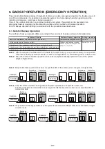
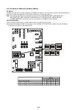
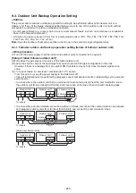
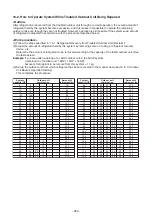
When vacuuming in the repaired outdoor unit, follow the procedure described below.
<Work procedure>
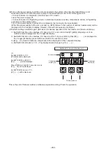
(1) Follow the procedure below to fully open PMV 1, 2, 3, and 4 and turn off the outdoor unit within 2 minutes
after the operation is completed.
Note)
The PMV fully open operation by the following operation will return to fully closed after 2 minutes.
1. Set [SW01/SW02/SW03] on the interface board to [2/1/3], and after [H.r] […………… is displayed on the 7-
segment display, press [SW04] and hold for 5 seconds or more.
2. Press [SW06] and hold for 5 seconds or longer, and [P.1] [F o...] Is displayed on the 7-segment display.
(PMV1 fully open)
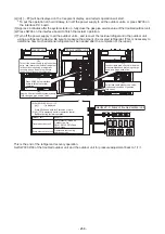
3. Set [SW01/SW02/SW03] on the interface board to [2/1/4], and after [P.2] […………… is displayed on the 7-
segment display, press [SW04] and hold for 5 seconds or longer, and [P.2][Fo...] Is displayed on the 7-
segment display. (PMV2 fully open)
4. 3. Similarly, set [SW01/SW02/SW03] to [2/1/5], set [SW01/SW02/SW03] to [2/1/6], press [SW04] and hold
for 5 seconds or more, and each have 7 segments.
[P.3][Fo...] (PMV3 fully open), [P.4][Fo...] (PMV4 fully open) are displayed on the display.
Note)
7-segment display and operation method: [P.x] [
...]
• The initial state is normal control, and […………… is displayed in *.
• When push SW4 is pressed for 5 seconds, it fully opens for 2 minutes, and [F o...] is displayed in *.
• Pressing again for 5 seconds displays an intermediate opening for 2 minutes, and [C o...] is
displayed in *.
• Pressing it again for 5 seconds closes it completely for 2 minutes and displays [Fc...] in *.
• Press again for 5 seconds to return to normal control.
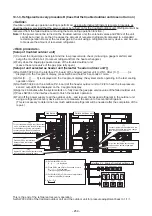
(2) Return [SW01/SW02/SW03] on the interface board to [1/1/1].
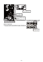
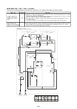
(3) Be sure to perform vacuuming in from the three check joints shown in the diagram below
(liquid pipe, discharge pipe and suction pipe).
TS1
TS3
Low-pressure
sensor
M
Fan
Fan motor
4-way valve
Oil separator
Outdoor Unit (22, 24HP)
Model: MMY-MUP2201
*
, MMY-MUP2401
*
SV
SV3D
TL1
High-pressure
sensor
Alt
M
Fan
Fan motor
TO
PMV1
TG3
TG1
PMV2
TG2
PMV3
TL2
TE1
Left side
Main heat exchanger
TE2
Left side
Sub heat exchanger
Right side
Main heat exchanger
TE3
Right side
Sub heat exchanger
Inverter heat sin
TD2
TK2
TK1)
(TD1)
SV
SV
TL3
Liquid side
Service valve
Gas side
Service valve
Subcool
Heat Exchanger
PMV4
Compressor 2
(Inverter)
Compressor 1
(Inverter)
SV41
High-
pressure
switch
High-
pressure
switch
SV42
SV
SV3F
Accumulator
SV
Symbol
SV
Solenoid
valve
Capillary
tube
Check
valve
Check
joint
Strainer
Temperature
sensor
Distributor
- 261 -
Содержание MMY-MUP0801HT7JP
Страница 32: ...2 8 5 USB isolate P C board MCC 1754 USB communication to I F CN01 USB connector CN02 screw 32 ...
Страница 309: ......

