background image

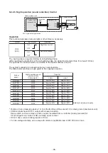
 Auto-off feature control

[Function]

• This function controls the indoor units individually. It is used when the start operation from outside is

unnecessary but the stop operation is necessary.

• A card switch box or card lock helps protect customers from forgetting to turn off the indoor unit.

(not including the following Card Input 2)

• It is connected with connector on the indoor control P.C. board, and switched with the Code No. and jumper

wire setup for use.

• Available connectors are CN61 or CN73.  For models without CN73, CN4 on the optional Application  control

kit (TCB-PCUC2E) can be used.

* Leaving-ON prevention control cannot be set with both CN61 and CN73 (CN4).

If both of them are set, CN73 (CN4) setting automatically turns to a factory default.

[Setup method]
(1) Wiring

(2) Code (DN) setup

Set Code (DN) according to “

Indoor unit function Code No. (DN Code) table

”.

* If you set “Card Input 1 to 4” for Code No. of CN61 and CN73, Code No. 000b setup becomes unavailable

and the functions of Card Input 3 or 4 in CN73 cannot be used.

1
2

1
2

3
4

3
4

5
6

5
6

CN61

T10

(YEL)

* In the figure, the contact indicates

a status that the card is taken out.

Power supply

Outside contact (Card switch box, etc: Procured locally)

Relay (procured locally)

Connecting to the CN61 connector

NOTE)

 Determine the cable length between the indoor control P.C. board and the relay within 3m.

Indoor control P.C. board

1
2

1
2

CN4

EXCT

(RED)

* In the figure, the contact indicates

a status that the card is taken out.

Power supply

Outside contact (Card switch box, etc: Procured locally)

Relay (procured locally)

Connecting to the Application control kit (TCB-PCUC2E, connector : CN4)

NOTE)

 Determine the cable length between the indoor control P.C. board and the relay within 3m.

Application control kit

Connector Jumper wire (J01) Code No. (DN)

Set data

Function

CN61

CN73

(CN4)

Short-circuit

(Factory default)

Short-circuit (Fact-

ory default) or

Open-circuit (cut)

Open-circuit (cut)

002E

000b

0000 (Factory default)

0001

0003

0000 (Factory default)

0001

0003

0000 (Factory default)

0002

0004

"HA normal setup" (pulse)

"Card Input 1" setup

"Card Input 2" setup

"HA normal setup" (Static)

"Card Input 3" setup

"Card Input 4" setup

"EXCT demand" setup (Forced thermostat-OFF)

"Card Input 3" setup

"Card Input 4" setup

- 84 -

Содержание MMY-MUP0801HT7JP

Страница 1: ...T7 J P MMY MUP2201HT7 J P MMY MUP2401HT7 J P MMY MUP0801HT8 J P MMY MUP1001HT8 J P MMY MUP1201HT8 J P MMY MUP1401HT8 J P MMY MUP14A1HT8 J P MMY MUP1601HT8 J P MMY MUP1801HT8 J P MMY MUP2001HT8 J P MMY MUP2201HT8 J P MMY MUP2401HT8 J P MMY MUP0801HT8P A MMY MUP1001HT8P A MMY MUP1201HT8P A MMY MUP1401HT8P A MMY MUP14A1HT8P A MMY MUP1601HT8P A MMY MUP1801HT8P A MMY MUP2001HT8P A MMY MUP2201HT8P A MMY...

Страница 2: ...E 47 6 APPLIED CONTROL AND FUNCTIONS 67 6 6 2 Test Operation of Indoor Unit 69 6 3 Method to Set Indoor Unit Function DN Code 70 6 4 Method to set Outdoor Unit Function Code No O DN 77 6 5 Applied Control of Indoor Unit 82 6 6 1 Outdoor Fan High Static Pressure Shift 86 6 6 2 Priority Operation Mode Setting 87 6 6 3 Applied Control of Outdoor Unit 90 6 7 Notice Code 101 6 8 System Cooperation Defr...

Страница 3: ...C tag Communication 168 8 TROUBLESHOOTING 169 8 1 Overview 169 8 2 Troubleshooting method 170 8 3 Troubleshooting based on information displayed on remote controller 176 8 4 Check Codes Displayed on Remote Controller and SMMS u Outdoor Unit 7 Segment Display on I F Board and Locations to Be Checked 180 8 5 Diagnosis procedure for each check code 195 8 6 7 Segment Display Function 226 8 7 Oil Level...

Страница 4: ...t of service parts Inverter 285 13 1 2 Configuration of inverter assembly 286 13 1 3 Interface P C Board MCC 1747 Replacement Procedure 289 13 1 4 Compressor P C Board MCC 1729 Replacement Procedure 290 13 1 5 Fan Motor P C Board MCC 1734 Replacement Procedure 292 13 1 6 Noise Filter P C Board 1 MCC 1748 Replacement Procedure 293 13 1 7 Noise Filter P C Board 2 MCC 1748 Replacement Procedure 294 1...

Страница 5: ...odel SVM 16044 A10 2006 A10 033 Slim Duct Type MMD UP 1SPHY E Made in China model MMD AP 4SPH1 E TR Made in Japan model MMD AP 6SPH1 E TR Made in Japan model A10 033 SVM 20095 Under Ceiling Type MMC UP 1HP E TR Made in Thailand model MMC AP 8HP E Made in Thailand model SVM 17015 A10 2004 Floor Standing Cabinet Type MML UP 1H E TR Made in Japan model MML AP 4H1 E TR Made in Japan model A10 033 A10 ...

Страница 6: ...ied service person who is allowed to work at heights has been trained in matters relating to working at heights with the air conditioners made by Toshiba Carrier Corporation or alternatively he or she has been instructed in such matters by an individual or individuals who have been trained and is thus thoroughly acquainted with the knowledge related to this work The qualified installer is a person...

Страница 7: ...uted Indicates possibilities assumed that a danger causing a death or serious injury of the repair engineers the third parties and the users due to troubles of the product after work when an incorrect work has been executed Indicates contents assumed that an injury or property damage may be caused on the repair engineers the third parties and the users due to troubles of the product after work whe...

Страница 8: ... noticed that some kind of trouble such as when a check code display has appeared there is a smell of burning abnormal sounds are heard the air conditioner fails to cool or heat or water is leaking has occurred in the air conditioner do not touch the air conditioner yourself but set the circuit breaker to the OFF position and contact a qualified service person Take steps to ensure that the power w...

Страница 9: ...lle of the indoor unit to undertake work When working at heights use a ladder which complies with the ISO 14122 standard and follow the procedure in the ladder s instructions Also wear a helmet for use in industry as protective gear to undertake the work Before working at heights put a sign in place so that no one will approach the work location before proceeding with the work Parts and other obje...

Страница 10: ...e of the service port is changed from one of the former R22 Do not use any refrigerant different from the one specified for complement or replacement Otherwise abnormally high pressure may be generated in the refrigeration cycle which may result in a failure or explosion of the product or an injury to your body For an air conditioner which uses R410A never use other refrigerant than R410A For an a...

Страница 11: ...h a way that it is not slack For the installation moving reinstallation work follow to the Installation Manual If an incorrect installation is done a trouble of the refrigerating cycle water leak electric shock or fire is caused Check after repair Once the repair work has been completed check for refrigerant leaks and check the insulation resistance and water drainage Then perform a trial run to c...

Страница 12: ...nother outdoor unit Capacity overflow may occur on the terminal block and may result in fire Do not install the air conditioner in a location that may be subject to a risk of expire to a combustible gas If a combustible gas leaks and becomes concentrated around the unit a fire may occur Install the indoor unit at least 2 5 m above the floor level since otherwise the users may injure themselves or ...

Страница 13: ...materials and work with great attention so that water and others do not mix in because pipes are affected by impurities such as water oxide scales oil etc Use the clean pipes Be sure to braze with flowing nitrogen gas Never use gas other than nitrogen gas 4 For the earth protection use a vacuum pump for air purge 5 R410A refrigerant is a zeotropic mixture type refrigerant Therefore use liquid type...

Страница 14: ...frigerant Unusable Use the Refrigerant charging balance Gas leak detector Checking gas leak Exclusive to R410A Vacuum pump Vacuum drying Usable if a counter flow preventive adapter is attached R22 Existing article Vacuum drying Vacuum pump with counter flow Usable by adjusting size Flare processing of pipes Flare tool R22 Existing article Bending processing of pipes Bender Refrigerant recovery dev...

Страница 15: ...ter indicates U series model Other than U series MMY MAP MCY MHP Indoor unit MM UP This letter indicates U series model Other than U series MM AP Wired remote controller RBC A U This letter indicates U series model Other than U series Remote sensor TCB TC U This letter indicates U series model Other than U series Wireless remote controller kit receiver unit U series outdoor unit SMMS u MMY MUP Oth...

Страница 16: ... PS PD 63H1 P 1L1 2T1 Mg CTT 5L3 3L2 4T2 6T3 Inverter P C Board Compressor Noise filter P C Board Symbol MCC 1729 MCC 1748 MCC 1734 MCC 1747 Parts name Interface Control P C Board Inverter P C Board Fan P C Board Connector Push button switch Rotary switch 2 way valve coil Pulse motor valve Main Compressor Dip switch 63A 600VAC 4 way valve coil High pressure switch SW01 SW02 SW03 63H1 CN F01 F02 SW...

Страница 17: ...t t t t t PS PD 63H1 P 1L1 2T1 Mg CTT 5L3 3L2 4T2 6T3 Inverter P C Board Compressor Noise filter P C Board Symbol MCC 1729 MCC 1748 MCC 1734 MCC 1747 Parts name Interface Control P C Board Inverter P C Board Fan P C Board Connector Push button switch Rotary switch 2 way valve coil Pulse motor valve Main Compressor Dip switch 63A 600VAC 4 way valve coil High pressure switch SW01 SW02 SW03 63H1 CN F...

Страница 18: ...2 4 3 CN305 WHI RED GRN BLU GRN BLU WHI RED 3 CN500 3 CN513 CN514 CN501 CN600 FM1 CN512 CN510 CN511 Uv Uh Uv Uh RED M CN303 5 PMV4 CN378 WHI CN381 WHI CN502 WHI t 2 1 YEL TO CN507 TO OUTDOOR UNIT 5 1 4 2 3 6 WHI SV3F SV3D SV41 CN324 2 3 4 5 6 CN910 WHI 5 RB CN01 CN02 BLK WHI RED BLU 3 2 2 2 S Uc Uc S 5 4 3 2 HEATER1 2 1 2 1 t 2 1 TD1 t 4 3 TK1 6 5 8 7 3 2 1 4 TG1 TG2 5 7 6 9 8 TE1 TE2 t 4 3 TS1 t ...

Страница 19: ...1201K4FB 10UC Output 9 7kW 1 1 Compressor LA1201K4FB 10UC Output 11 5kW 1 1 Compressor LA1201K4FB 10UC Output 13 0kW 1 1 Compressor LA771A3TB 20M Output 7 9kW 2 1 Compressor LA771A3TB 20M Output 9 5kW 2 2 4 way valve coil SHF AC220 240V 50Hz AC220 240V 50Hz SV3D SV41 SV42 AC220 240V 50Hz SV3F 4 Pulse motor valve coil PAM PMV1 4 Pulse motor valve coil HAM PMV2 3 4 Pulse motor valve coil UKV PMV4 5 ...

Страница 20: ... 10UC Output 9 7kW 1 1 Compressor LA1201K4FB 10UC Output 11 5kW 1 1 Compressor LA1201K4FB 10UC Output 13 0kW 1 1 Compressor LA771A3TB 20M Output 7 9kW 2 1 Compressor LA771A3TB 20M Output 9 5kW 2 2 4 way valve coil SHF AC208 230V 60Hz AC208 230V 60Hz SV3D SV41 SV42 AC208 230V 60Hz SV3F 4 Pulse motor valve coil PAM PMV1 4 Pulse motor valve coil HAM PMV2 3 4 Pulse motor valve coil UKV PMV4 5 High pre...

Страница 21: ...Output 11 4kW 1 1 Compressor LA1201K4FB 10UC Output 13 2kW 1 1 Compressor LA1201K4FB 10UC Output 14 9kW 1 1 Compressor LA771A3TB 20M Output 9 0kW 2 1 Compressor LA771A3TB 20M Output 10 7kW 2 2 4 way valve coil SHF AC220 240V 50Hz AC220 240V 50Hz SV3D SV41 SV42 AC220 240V 50Hz SV3F 4 Pulse motor valve coil PAM PMV1 4 Pulse motor valve coil HAM PMV2 3 4 Pulse motor valve coil UKV PMV4 5 High pressur...

Страница 22: ... UKV A376 Position Resistance value White Red COM Yellow Red COM Orange Red COM Blue Red COM at 20 C 5 PMV Pulse Motor Valve coil Measure each winding resistance by digital tester Model PAM MD12TF Position Resistance value White Red COM Yellow Red COM Orange Red COM Blue Red COM at 20 C 6 4 way valve coil Measure each winding resistance by digital tester Model SQ A2522G at 20 C 7 2 way valve coil ...

Страница 23: ...or 1 Inverter P C board for Compressor 2 Inverter P C board for fan Magnet Contactor Magnet Contactor PTC Thermistor JXO 6004 AC600V 75A 4P 2 MCC 1748 3 MCC 1748 0 9mH AC460V 50A 4 5 MCC 1747 6 MCC 1729 50A 7 MCC 1729 75A 8 MCC 1734 FC 1S FC 2S MZ32 101R 9 10 11 13A AC500V MMY MUP0801 MMY MUP1001 MMY MUP1201 MMY MUP1401 MMY MUP1601 MMY MUP1801 MMY MUP2001 MMY MUP2201 MMY MUP2401 MMY MUP14A1 23 ...

Страница 24: ...UP14A1 MMY MUP1601 MMY MUP1801 MMY MUP2001 22 24HP Model MMY MUP2201 MMY MUP2401 Low pressure sensor Check joint Low pressure TO sensor Check joint Liquid pipe Accumulator High pressure sensor High pressure SW Check joint High pressure Compressor High pressure SW Compressor Low pressure sensor Accumulator TO sensor Check joint Liquid pipe High pressure sensor High pressure SW1 High pressure SW2 Co...

Страница 25: ... C board for Compressor 1 MCC 1729 Communication terminal block Power supply terminal block Noise Filter P C board 1 MCC 1748 Magnet Thermistor Contactor Remove the Interface P C board sub assembly The Interface P C board sub assembly Interface P C board MCC 1747 Inverter P C board for fan MCC 1734 50 25 ...

Страница 26: ...tion terminal block Power supply terminal block Noise Filter P C board 2 MCC 1748 Thermistor Magnet Contactor Remove the Interface P C board sub assembly The Interface P C board sub assembly Interface P C board MCC 1747 75 Inverter P C board for fan 2 MCC 1734 Inverter P C board for fan 1 MCC 1734 Line Filter 26 ...

Страница 27: ...e Filter P C board 2 MCC 1748 Thermistor 1 Magnet Contactor 1 Remove the Interface P C board sub assembly The Interface P C board sub assembly Interface P C board MCC 1747 Inverter P C board for fan 1 MCC 1734 50 Inverter P C board for fan 2 MCC 1734 Inverter P C board for Compressor 1 1 MCC 1729 Magnet Contactor 2 Thermistor 2 Line Filter 27 ...

Страница 28: ...ase heater 1 CN331 Comp case heater 2 CN332 Base plate heater CN335 Sensor input CN502 㧙 㧙 TK1 TD1 CN507 TO CN378 TL3 TL2 TL1 TS3 TS1 CN380 TD2 TK2 CN384 TG3 TE3 CN381 TE2 TE1 TG2 TG1 PD sensor CN501 PS sensor CN500 SW101 102 103 SW104 105 106 TERMINATOR SW100 190mm UART communication CN600 NFC CN851 USB CN860 Detection of power supply open phase and miswiring CN910 59 59 59 5 0 0 0 0 0 0 10 10 10...

Страница 29: ... F CN103 Power supply Input L3 CN03 190mm Power supply Input L1 CN01 Power supply Input L2 CN02 Power supply Input N CN04 Power supply Output L3 CN23 Power supply Output L1 Power supply Output L2 CN22 Power supply output to I F CN101 Power supply output to Comp CN102 Vcc output to I F CN103 1290W 1Comp 2Fan model K4 Compressor 14A 16 18 20HP 1290W 2Comp 2Fan model A3 Compressor 22 24HP 990W 1Comp ...

Страница 30: ...AN CN22 Vdc output to FAN CN21 Compressor output W phase CN203 Compressor output V phase CN202 Compressor output U phase CN201 Vcc output to FAN CN103 8pin 4pin White White 190mm 190mm For inverter address setting SW800 1290W 2Comp 2Fan model A3 Compressor 22 24HP 990W 1Comp 1Fan model A3 Compressor 8 10 12 14HP 1290W 1Comp 2Fan model K4 Compressor 14A 16 18 20HP 0 0 0 0 0 0 0 0 0 6 0 0 0 0 4 614 ...

Страница 31: ...ard for fan MCC 1734 190mm UART communication CN802 CN803 Vcc input CN100 Vcc output CN101 Vdc input from COMP CN01 Vdc input from COMP CN02 For inverter address setting SW800 Fan motor output CN301 0 0 0 0 0 0 0 0 59 0 31 ...

Страница 32: ...2 8 5 USB isolate P C board MCC 1754 USB communication to I F CN01 USB connector CN02 screw 32 ...

Страница 33: ...or Low pressure sensor Accumulator Liquid side Service valve Gas side Service valve Subcool Heat exchanger SV Solenoid valve Capillary tube Check valve Check joint Strainer Temperature sensor Symbol Distributor SV SV3F TE1 TG2 TG1 Inverter heat sink Sub heat exchanger PMV2 Main heat exchanger TL2 TL1 TK1 TD1 SV Compressor Inverter SV41 High pressure switch SV3D SV Oil separator 33 ...

Страница 34: ...tor High pressure sensor M Fan Fan motor TL1 PMV1 TG3 TG1 PMV2 TG2 PMV3 TE1 Left side Main heat exchanger TE2 Left side Sub heat exchanger Right side Main heat exchanger TE3 RIght side Sub heat exchanger INV heat sink M Fan Fan motor TO TK1 TD1 SV TL3 Liquid side Service valve Gas side Service valve Subcool Heat Exchanger PMV4 Compressor Inverter SV41 High pressure switch SV3D Accumulator SV Oil s...

Страница 35: ...e sensor A l t M Fan Fan motor TO PMV1 TG3 TG1 PMV2 TG2 PMV3 TE1 Left side Main heat exchanger TE2 Left side Sub heat exchanger Right side Main heat exchanger TE3 Right side Sub heat exchanger Inverter heat sin TD2 TK2 TK1 TD1 SV SV TL3 Liquid side Service valve Gas side Service valve Subcool Heat Exchanger PMV4 Compressor 2 Inverter Compressor 1 Inverter SV41 High pressure switch High pressure sw...

Страница 36: ...peration PMV4 Connector CN303㧦RED 1 Controls superheat and subcool of the sub cooling heat exchanger 2 Liquid bypass function for discharge temperature releases cooling bypass function 4 Way valve Connector CN317㧦ORN 1 Cooling Heating change 2 Reverses Defrost Temperature Sensor TD1 TD2 TD1 Connector CN502㧦WHI TD2 Connector CN380㧦BLK 1 Protection of compressor discharge temperature 2 Used for disc...

Страница 37: ... 3 Recovers refrigerant oil in cooling operation 4 Recovers refrigerant oil in heating operation Temp Sensor Connector CN104 2P Yellow 1 Detects indoor return air temperature Functional outline 2 TC1 Connector CN100 3P Brown 1 Controls PMV superheat in cooling operation 3 TC2 4 TCJ Connector CN101 2P Black 1 Controls PMV subcool in heating operation Connector CN102 2P Red 1 Controls PMV superheat ...

Страница 38: ...rigerant 38 HP system described in the example of 24 HP 14 HP Condensate liquid refrigerant Evaporative gas refrigerant Low pressure Low pressure circuit Refrigerant recover line TK1 TK2 PMV3 PMV4 Oil separator Compressor 1 Inverter Compressor 2 Inverter SV SV42 SV3F SV SV SV Gas side Service valve TC2 TCJ TC1 Cooling TC2 TCJ TC1 Cooling TC2 TCJ TC1 Cooling Follower Unit MMY MUP1401 M Fan Main hea...

Страница 39: ...pressure switch High pressure sensor 4 way valve Low pressure sensor Accumulator TS1 TL2 PMV1 TG3 TS3 SV3D SV41 TD1 TD2 TL3 Liquid side Service valve TC2 TCJ TC1 Cooling Outdoor Unit High pressure gas refrigerant Condensate liquid refrigerant Evaporative gas refrigerant Low pressure Low pressure circuit Refrigerant recover line TK1 TK2 PMV3 PMV4 Oil separator Compressor 1 Inverter Compressor 2 Inv...

Страница 40: ...ibed in the example of 24 HP 14 HP Condensate liquid refrigerant Evaporative gas refrigerant Low pressure Low pressure circuit Refrigerant recover line TK1 TK2 PMV3 PMV4 Oil separator Compressor 1 Inverter Compressor 2 Inverter SV SV42 SV3F SV SV SV Gas side Service valve TC2 TCJ TC1 Heating TC2 TC1 Heating TC2 TCJ TC1 Heating Follower Unit MMY MUP1401 M Fan Main heat exchanger Main heat exchanger...

Страница 41: ...gas refrigerant Low pressure Low pressure circuit Refrigerant recover line TK1 TK2 PMV3 PMV4 Oil separator Compressor 1 Inverter Compressor 2 Inverter SV SV42 SV3F SV SV SV Gas side Service valve TC2 TCJ TC1 Heating TC2 TCJ TC1 Heating TC2 TCJ TC1 Heating Follower Unit MMY MUP1401 Heating Unit M Fan Main heat exchanger Main heat exchanger Main heat exchanger Sub heat exchanger Sub heat exchanger S...

Страница 42: ...anger Main heat exchanger Sub heat exchanger Sub heat exchanger Sub heat exchanger TE1 TG1 TG2 TE2 TL1 Inverter heat sink Subcool Heat Exchanger High pressure sensor 4 way valve Low pressure sensor TS1 TL2 TO PMV1 TO TS3 TL3 PMV2 PMV4 Trouble header outdoor unit High pressure gas refrigerant 38 HP system described in the example of 24 HP 14 HP Condensate liquid refrigerant Evaporative gas refriger...

Страница 43: ...Main heat exchanger Sub heat exchanger Sub heat exchanger Sub heat exchanger TE1 TG1 TG2 TE2 TL1 Inverter heat sink Subcool Heat Exchanger High pressure sensor 4 way valve Low pressure sensor TS1 TL2 TO PMV1 TO TS3 TL3 PMV2 PMV4 Trouble header outdoor unit High pressure gas refrigerant 38 HP system described in the example of 24 HP 14 HP Condensate liquid refrigerant Evaporative gas refrigerant Lo...

Страница 44: ...anger Main heat exchanger Sub heat exchanger Sub heat exchanger Sub heat exchanger TE1 TG1 TG2 TE2 TL1 Inverter heat sink Subcool Heat Exchanger High pressure sensor 4 way valve Low pressure sensor TS1 TL2 TO PMV1 TO TS3 TL3 PMV2 PMV4 Trouble header outdoor unit High pressure gas refrigerant 38 HP system described in the example of 24 HP 14 HP Condensate liquid refrigerant Evaporative gas refriger...

Страница 45: ... heat exchanger Sub heat exchanger Sub heat exchanger Sub heat exchanger TE1 TG1 TG2 TE2 TL1 Inverter heat sink Subcool Heat Exchanger High pressure sensor 4 way valve Low pressure sensor TS1 TL2 TO PMV1 TO TS3 TL3 PMV2 PMV4 Trouble header outdoor unit High pressure gas refrigerant 38 HP system described in the example of 24 HP 14 HP Condensate liquid refrigerant Evaporative gas refrigerant Low pr...

Страница 46: ...mpressor 2 Inverter SV SV42 SV3F SV SV SV TC2 TCJ TC1 Cooling TC2 TCJ TC1 Cooling TC2 TCJ TC1 Cooling Follower Unit MMY MUP1401 M FAN On Main heat exchanger Main heat exchanger Main heat exchanger Sub heat exchanger Sub heat exchanger Sub heat exchanger TE1 TG1 TG2 TE2 TL1 Inverter heat sink Subcool Heat Exchanger High pressure sensor 4 way valve Low pressure sensor TS1 TL2 TO PMV1 Open TO TS3 TL3...

Страница 47: ...F state or upon being tuned off normally or shut down due to an abnormality 2 PMV 4 control 1 During cooling the pulse count of a PMV 4 pulse motor valve 4 is controlled between 30 pls and 350 pls The PMV 4 opening is controlled on the basis of measurements provided by the TL3 temperature sensor and Pd sensor subcool control or TS3 temperature sensor and Ps sensor superheat control 2 During heatin...

Страница 48: ...d off Zone A Lowest mode timer count for forced compressor shutdown Zone B 2 15 seconds down to lowest mode Zone C 1 15 seconds down to lowest mode Zone D Hold staying at current mode Zone E 1 15 seconds up to highest mode Zone F Highest mode TE1 temperature C 3 Upper limit shift correction control in outdoor fan mode while operating in heating mode This is a control that lowers the upper limit of...

Страница 49: ...edicted TK TK 10 C the oil level is appropriate When predicted TK TK 10 C the oil level is insufficient The outdoor rotation control may be performed even when the insufficient refrigerant state is not released even if the indoor refrigerant recovery control is performed 4 Oil level detection control 1 TK1 2 sensor detection temperature and prediction TK1 2 sensor temperature is used to judge whet...

Страница 50: ...ery control Since the indoor unit that is stopped during heating operation closes the PMV liquid refrigerant may accumulate in the heat exchanger resulting in a refrigerant shortage condition This control is to recover the liquid refrigerant to return it to the outdoor unit when a refrigerant shortage is detected The PMV opening of the stopped indoor unit is slightly opened to return the refrigera...

Страница 51: ...ry Control Individual defrost method outdoor unit is combined system 2 Outdoor unit grouping method The outdoor unit is divided into Gr1 and Gr2 when the power is turned on TE sensor detection temperature is the lowest temperature of TE1 TE2 TE3 Frosting temperature is 1 5 C After the power is turned on for the first time the defrosting operation is continued for 25 minutes below the frosting temp...

Страница 52: ... a control to suppress the high pressure rise during cooling operation and heating operation This control is performed independently by the header unit and each follower unit Control condition Compressor ON Control content When Pd P1 SV4 x is turned on When Pd P2 SV4 x is turned off P1 and P2 of each outdoor unit are as follows Pd control point Heating Cooling Release condition When the system is ...

Страница 53: ...unit 1 Control details Compressors are shut down when Pd reaches or exceeds P0 The Pd control point P0 is switched according to the start priority of the outdoor unit The compressor restart prevention timer 2 minutes 30 seconds is set and the control terminated 11 Case heater control This control function is aimed at preventing the accumulation of refrigerant in those case and is performed by all ...

Страница 54: ...ation when the TH sensor temperature exceeds 93 C When the above is stopped the abnormal count is set to 1 and it restarts after 2 minutes and 30 seconds If you continue the operation for 10 minutes or more after restarting the trouble count will be cleared A trouble is confirmed with a trouble count of 4 HP 24 22 20 18 16 14 12 10 8 Maximum current 27 00A 25 50A 36 00A 34 00A 30 50A 27 50A 24 50A...

Страница 55: ...ased on the temperature of the TC sensor of indoor unit When suction pressure Ps decreases the compressor frequency Hz may be decreased due to cooling capacity control When discharge temperature TD is lower than 60 the compressor frequency Hz may be increased due to indoor unit command 2 PMV Pulse motor Valve When power is turned on the PMV will initialize and make a knocking sound If there is no ...

Страница 56: ...d STOP FAN COOL DRY HEAT AUTO Heat recovery system outdoor unit type Control outline Operation stops Fan operation Cooling operation Dry operation Heating operation TA and Ts automatically select COOL HEAT operation mode for operation The operation is performed as shown in the following figure according to TA value at the first time only In the range of Ts 1 TA Ts 1 Cooling thermostat OFF Fan Setu...

Страница 57: ... as shown below When TA exceeds Tsh by 1 5 for 10 minutes the operation is thermostat OFF then the heating operation thermostat OFF is changed to cooling operation When TA is less than Tsh by 1 5 for 10 minutes the operation is thermostat OFF then the cooling operation thermostat OFF is changed to heating operation 2 For the automatic capacity control after judgment of cooling heating refer to ite...

Страница 58: ...hen cooling operation has started select a down ward slope for the air speed that is the high position If the temperature is just on the difference boundary the air speed is not changed HEAT indicate the value when the remote controller sensor is worked If the air speed has been changed once it is not changed for 1 minute However when the air speed changed the air speed changes When heating operat...

Страница 59: ...ult Type 1 Type 3 0000 0001 0003 OFF OFF ON OFF OFF ON Type 6 0006 ON ON COOL HEAT COOL HEAT COOL COOL HEAT HEAT HH H H L L LL HH H H L L LL HH H H L L LL HH H H L L LL HH H H L L LL HH H H L L LL HH H H L L LL HH H H L L LL 4 way compact 4 way only UP015 2 way 1 way SH Air speed selection of UP012 or less and UP018 for Compact 4 way are only Standard CODE No 5d SW501 1 2 Tap F1 F2 F3 F4 F5 F6 F7 ...

Страница 60: ...ed and held When shifting to M zone again the timer count restarts and continues If L zone is detected the timer is cleared and the operation returns to normal operation Reset conditions 1 TC1 12 C and TCJ 12 C 2 20 minutes passed after stop P1 Q1 C a K J P2 Q2 C L N M value When the power supply is turned on the forced thermostat becomes OFF if the temperature is less than this indicated temperat...

Страница 61: ...ing if the float switch is operated the outdoor unit will stop operating but the drain pump will keep continuously operating After that the check code is issued 3 When the drain pump stops operating if the float switch is operated the outdoor unit will stop and the drain pump will start operating After the float switch is being operating for roughly 5 minutes the check code will be issued 1 When t...

Страница 62: ...he remote controller at the indoor unit side is possible according to setting at the central controller side 2 Setting contents Remarks Operation standby display No display for wireless type remote controller Heating standby display Operation possible Operation impossible Selection of central control mode 17 Operation from TCC LINK central control Individual Central 1 Central 2 Central 3 Central 4...

Страница 63: ... is repeated In all operations Repeats In group operation the louver positions can be set up collectively or individually 3 When the unit stopped or the warning was output the louver is automatically set to full closed position 4 When PRE HEAT Heating ready is displayed Heating operation started or defrost operation is performed heating thermostat is off or self cleaning is performed the louver is...

Страница 64: ...llustration during normal operation the air direction of the least No among the louvers which are block set is displayed While individual air direction is being set the remote controller operation Illustration of air direction and operation of the real machine are linked When selecting a case Louver select button is not pushed or louver No is not displayed the air directions of all the louvers are...

Страница 65: ...cting the Swing mode Dual swing or Cycle swing the following numerals is displayed at the center of the remote controller screen for approx 3 seconds when SWING FIX button was pushed to select SWING No display for the standard swing In the case of RBC AMT Remarks Carr Subject model 4 way cassette Compact 4 way y out setting operation during stop of the unit otherwise the unit stops operation Dual ...

Страница 66: ...n 19 DC motor 1 When the fan starts positioning is performed for the starter and the rotor Vibrate slightly 2 DC motor operates according to the command from the indoor controller Note If the fan rotates by entry of outside air etc while the air conditioner stopped the indoor unit may operate as the fan motor stops Note If the fan lock was detected the operation of the indoor unit stops and the ch...

Страница 67: ...tal and Drain pump ON without communication with outdoor and remote controller CN72 White DISP Exhibition mode DISP mode input 0V Communication is available by indoor unit and remote controller only When the power is turned on Shortening time of timer Always CN309 Yellow Output power supply for option AC230V AC230V This can be used as power supply for option devices CN501 White For service CN81 Bl...

Страница 68: ...o the outside㧕 Perform the settings having option abnormal input from the remote controller DN 2A 0002 0001 CN071 White Check mode input 0V CHK Operation check Use for operation check of indoor unit Performs operation of indoor fan H Louver horizontal and Drain pump ON without communication with outdoor and remote controller㧕 CN072 White DISP mode input 0V DISP Exhibition mode Communication is ava...

Страница 69: ...normal time the minimum opening degree 30pls of the indoor PMV can be set only when both CHK pin CN71 and DISP pin CN72 on the indoor P C board are short circuited If the short circuit at DISP pin CN72 is opened the indoor PMV will be at the maximum opening degree 1500pls Fan motor Indoor PMV Louver Communication P C board LED Short circuit of CHK pin Normal time DISP pin short circuit H Min openi...

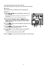
Страница 70: ...ol Then the fan and louver of the selected indoor unit move 2 Each time the Select unit side of the UNIT LOUVER button is pressed one of the indoor unit Nos under group control is displayed in turn Then the fan and louver of the selected indoor unit move 3 Use the button to select the CODE No DN code of the desired function 4 Use the button to select the desired SET DATA associated with the select...

Страница 71: ...cted indoor unit 4 Push the menu button to make Code No 04 flash Change Code No 04 with setting button 5 Push the menu button to make Set data 0001 flash Change Set data 0001 with setting button Priority set 0001 No priority set 0000 6 Push OFF timer button to complete the set up To change other settings of the selected indoor unit repeat from Procedure 4 7 When all the settings have been complete...

Страница 72: ...1 ޓ list type Line address 0001 No 1 unit to 0064 No 30 unit TCC LINK 00Un 0099 Unfixed 0001 No 1 unit to 0128 No 128 unit TU2C LINK 00Un Unfixed When using U series remote controller 0099 Unfixed Other than U series remote controller Indoor unit address 0001 No 1 unit to 0064 No 64 unit TCC LINK 00Un 0099 Unfixed 0001 No 1 unit to 0128 No 128 unit TU2C LINK 00Un Unfixed When using U series remote...

Страница 73: ...ving mode can be set by the remote controller 0000 Invalid 0001 Valid 0001 Valid d0 E6 Wireless remote controller A B selection 0000 A 0001 B 0000 A F0 Swing mode 0001 Standard 0003 Cycle swing 0002 Dual swing 0001 Standard F1 Louver fixed position Louver No 1 0000 Release 0001 Horizontal discharge position 0000 Not fixed 0005 Downward discharge position F2 Louver fixed position Louver No 2 0000 R...

Страница 74: ...ller use is impossible 0000 No central device control 103 Remote controller 0000䋺Use 0001䋺Do not use 0000㧦Use 1 Display order of 00Un and 0099 varies depending on remote controller models or communication types 2 Communication protocol can be automatically switched with the setup in the outdoor unit during installation For Central control address DN 03 Indoor unit address DN 13 FS unit address DN ...

Страница 75: ...024 to 030 Factory default 0001 30 Pa UP007 to 018 Factory default 0002 65 Pa 0003 50 Pa UP036 to 056 Factory default 0004 80 Pa 0005 100 Pa 0006 120 Pa Slim Duct type Set data External static pressure 0000 10 Pa Standard Factory default 0001 20 Pa High static pressure 1 0003 35 Pa High static pressure 2 0006 50 Pa High static pressure 3 Concealed Duct High Static Pressure Type 6 HP or less Set da...

Страница 76: ...Floor standing concealed MML UP BH 0013 Floor standing type MMF UP H 0014 Compact 4 way cassette MMU UP MH 0016 Fresh Air Intake indoor unit Duct type MMD UP HFP 0018 Bi flow Console MML UP NHP 0060 Hot Water Module MMW UP LQ Indoor Unit Capacity DN code 11 Value Capacity 0000 Invalid 0001 007 type 0002 008 type 0003 009 type 0004 010 type 0005 012 type 0006 014 type 0007 015 type 0008 017 type 00...

Страница 77: ...nce the code Press and hold SW05 to advance in 5 steps Press SW06 to return the code Press and hold SW05 to return in 5 steps 5 When SW04 is pressed the 7 segment display blinks d and the setting data being set is displayed 6 Change setting data with SW05 or SW06 Press SW05 to advance the data Press SW06 to return the setting data 7 Push and hold SW04 for more than 2 seconds When the flashing stop...

Страница 78: ...shes as shown in the figure ALL is displayed as outdoor unit numbers during initial communication immediately after the power has been turned on 2 Each time setting button is pushed outdoor unit numbers in the group control change cyclically Select the outdoor unit to change settings for The fan of the selected outdoor unit runs The outdoor unit can be confirmed for which to change settings 3 Push...

Страница 79: ...other settings of the selected outdoor unit repeat from Procedure 4 7 When all the settings have been completed push ON OFF button to finish the settings Return to the normal mode SETTING flashes and then the display content disappears and the air conditioner enters the normal stop mode The remote controller is unavailable while SETTING is flashing To change settings of another outdoor unit repeat...

Страница 80: ...000 0h 0001 to 0063 1000 h to 63000 h Compressor Maintenance Period Time 0000 0h 0000 Capacity demand 0001 Power demand 009 Capacity Power Demand Control 0000 Capacity demand Code range 0A 0C 0000 to 0255 1 kW to 255 kW 0B 0D 0000 to 0099 0 00 kW to 0 99 kW 00A Power consumption upper limit standard value setting Heating For power demand _High 0000 0kW Setting Value during Demand Control for deman...

Страница 81: ...nit 0001 System abnormal stop 0000 System continuous operation Stop the corresponding indoor unit 01d System cooperation defrosting settings 1 number cooperating 0000 None vassal 0002 2 system cooperation master unit set 01D 0002 or 0003 to outdoor unit set to master unit in outdoor DN code 01F 0001 Prohibition 0003 3 system cooperation master unit 0000 None vassal 01E System cooperation defrostin...

Страница 82: ...eration 3 Check code Output present while alarm e g serial communication trouble or operation of protective device for indoor outdoor unit being activated Wiring diagram of control system using Remote location ON OFF control box TCB IFCB 4E2 Input IFCB 4E2 No voltage ON OFF serial signal Output No voltage contact in operation and check code indication Contact capacity Max AC 240 V 0 5 A 1 2 3 4 5 ...

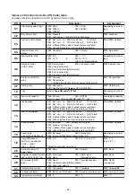
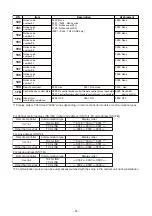
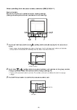
Страница 83: ...the selected indoor unit turns on 2 Every pushing UNIT LOUVER button left side of the button the indoor unit numbers in group control are displayed successively In this time the fan of the selected indoor unit only turns on 3 Using the setup temp or button specify the CODE No 31 4 Using the timer time or button select the SET DATA At shipment 0000 The setup data are as follows 5 Push button OK if ...

Страница 84: ...e used 1 2 1 2 3 4 3 4 5 6 5 6 CN61 T10 YEL In the figure the contact indicates a status that the card is taken out Power supply Outside contact Card switch box etc Procured locally Relay procured locally Connecting to the CN61 connector NOTE Determine the cable length between the indoor control P C board and the relay within 3m Indoor control P C board 1 2 1 2 CN4 EXCT RED In the figure the conta...

Страница 85: ...stat OFF EXCT Please refer to the manual of Application control kit for a detailed setting Code No DN Code No DN ON Status that card is inserted OFF Status that card is taken out Manual prohibition release Manual operation Card Input 1 Manual prohibition Operation stop Manual prohibition release Automatic operation Card Input 2 Manual prohibition Operation stop Operation status continues Do nothin...

Страница 86: ...hift Setup Change the outdoor DN code O DN 19 into Outdoor Fan High Static Pressure operation This function must be enabled with every discharge duct connected outdoor unit for both of the header and follower units Specifications Increase the speed of the propeller fan units on the outdoor fan to allow the installation of a duct with a maximum external static pressure not greater than specified in...

Страница 87: ...peration a single unit only 1 Outdoor unit setup method header unit Outdoor DN Code O DN Setting Operation O DN 18 0000 Priority heating factory default O DN 18 0001 Priority cooling O DN 18 0002 Priority operation based on No of units in operation priority given to the operation mode with the largest share of units in operation O DN 18 0003 Priority indoor unit priority given to the operation mod...

Страница 88: ... the position of this unit can be confirmed 3 Use the button to select the CODE No 04 4 Use the button to select the SET DATA 0001 Priority set 0001 No priority set 0000 Description Check code Duplicated indoor unit priority setting The unit is set to 0001 Duplicated indoor unit priority setting The unit is set to 0000 5 Push the button The setup is finished when the display changes from flashing ...

Страница 89: ...Push the menu button to make Code No 04 flash Change Code No 04 with setting button 5 Push the menu button to make Set data 0001 flash Change Set data 0001 with setting button Priority set 0001 No priority set 0000 6 Push OFF timer button to complete the set up To change other settings of the selected indoor unit repeat from Procedure 4 7 When all the settings have been completed push ON OFF butto...

Страница 90: ...e SW105 1 009 0 Factory default Power peak cut Control For one input function Limit a maximum capacity Header unit CN513 blue SW105 1 009 1 Power peak cut Control For one input function Limit a maximum power 2 Header unit CN513 blue SW105 2 009 0 Factory default Power peak cut Control Enhanced Function Limit a maximum capacity Header unit CN513 blue SW105 2 009 1 Power peak cut Control Enhanced Fu...

Страница 91: ...an be regulated with the outdoor DN Code O DN 00E Demand power peak cut control 2 stage switching SW105 bit1 OFF bit2 OFF Display relay SW105 Outdoor unit DN Code 00E SW1 Input Control item SW2 L1 Bit1 Bit2 Factory default 00E 15 00E 0 to 10 Input demand OFF signal to release the demand Outdoor unit DN Code O DN 00E X 0 1 2 3 4 5 6 7 8 9 10 100 95 90 85 80 75 70 65 60 55 50 15 factory default 0 fo...

Страница 92: ... or less 24 VAC 10 mA or more 1 A or less non conductive load When connecting a conductive load e g relay coil to the display relay load insert a surge killer CR for an AC power supply or a diode for preventing back electromotive force for a DC power supply on the bypass circuit PJ17 TB1 TB2 COM ON COM OFF CN513 SW105 Bit1 ON Bit2 OFF L1 SW1 ON OFF 1 2 3 4 ON OFF Connection cable Locally procured ...

Страница 93: ...it DN Code O DN 00F Y 0 1 2 3 4 5 6 7 8 factory default 9 10 100 95 90 85 80 75 70 65 60 55 50 15 0 forced stop Outdoor unit DN Code O DN 010 Z 0 1 2 3 4 factory default 5 6 7 8 9 10 100 95 90 85 80 75 70 65 60 55 50 15 0 forced stop PJ17 TB1 ON OFF TB2 COM ON COM OFF CN513 SW105 Bit1 OFF Bit2 ON L1 SW1 ON OFF 1 2 3 4 SW2 Connection cable Locally procured OPERATION L1 Display lamp ensuring power p...

Страница 94: ...t control does not function NOTE 3 Power consumption is estimated causing approx 5 difference from the actual power consumption To perform accurate power peak cut control use a demand controller and electric power meter NOTE 4 The power consumption of the indoor units is not included NOTE 5 When power consumption does not decrease or expected effects are not obtained change the upper limit value o...

Страница 95: ...or unit interface PCB Shield wire Terminal Input signal Operation COOL SW1 All indoor units operate together All indoor units operate together ON OFF ON OFF SW1 Operation input switch SW2 Stop input switch PJ17 CN512 TB1 SW1 SW2 COM HEAT COOL Locally procured Optional PCB Header outdoor unit Outdoor unit interface PCB Connection cable Shield wire Terminal Input signal Operation COOL SW1 Turns on a...

Страница 96: ...controller locally procured for CO Change Over contact or NO normally open contact DC12 V has a current limiting resistor of 3 3 For non voltage contacts use a relay with minimum applicable load of DC12V 3mA or less SW1 Night time signal switch PJ17 CN508 TB1 SW1 COM HEAT COOL Locally procured Optional PCB Header outdoor unit Outdoor unit interface PCB Connection cable Shield wire Terminal Input s...

Страница 97: ...t super slow blow rate Follow the remote controller Normal air blow operation Heating operation only allowed OFF ON or Thermostat OFF Air blow operation at blow rate set on remote control Follow the remote controller Normal heating operation Follow the remote controller Normal air blow operation Operation State O DN 008 1 Only operation modes and air blow operation selected on the P C board can be...

Страница 98: ...nnecting a conductive load e g relay coil to loads K1 and K2 insert a surge killer CR for an AC power supply or a diode for preventing back electromotive force for a DC power supply on the bypass circuit OUTPUT1 CN511 PJ20 OUTPUT2 OUTPUT3 TB1 L1 L2 1 2 5 6 4 3 C1 PS PS K1 K2 Optional PCB Locally procured See NOTE Header outdoor unit Outdoor unit interface PCB Shield wire C1 CN511 K1 K2 L1 L2 OUTPU...

Страница 99: ...erminal block Operation When a compressor is in operation a relay connected to the output terminal assigned to it is turned on closed When it is at rest the relay is turned off open The output terminals are named OUTPUT1 and OUTPUT2 from left to right when facing the front of the outdoor unit as shown in the diagram Note 1 Output Relay K1 K2 Contact Specifications Output terminals OUTPUT1 2 must s...

Страница 100: ...ply on the bypass circuit Electrical Rating 220 240 VAC 10 mA or more 1A or less 24 VAC 10 mA or more 1 A or less non conductive load OUTPUT1 CN514 PJ20 OUTPUT2 OUTPUT3 TB1 1 2 6 4 3 C2 K1 K2 K3 MONITOR Optional PCB Locally procured See NOTE Header outdoor unit Outdoor unit interface PCB Shield wire 5 off Relay open on Relay closed Function Operation rate FA OUTPUT2 OUTPUT1 Outdoor DN Code O DN O ...

Страница 101: ...ch DN Code You can set it on any of 180 to 189 A maximum 10 types of the notice codes can be set on a single indoor unit 2 A notice code mark will be displayed on the remote controller when any of the 10 notice codes set is received into the remote controller If the notice code that is not set is received a notice code mark is not displayed Set the notice code that you want from the remote control...

Страница 102: ...issued now Setting the SW01 SW02 SW03 to 1 1 14 respectively displays the notice code being issued from the outdoor unit on the 7 segment display 7 segment display n 1 Notice code Every time SW04 is pushed for 1 second the display changes and the second notice code or each subsequent code is displayed up to fifth code n 1 First to n 2 Second to to n 5 Fifth to n 1 First 2 Displaying the notice cod...

Страница 103: ...em II ends even if defrosting conditions are satisfied Defrosting is started after defrosting of system II ends Defrosting of system II ends During individual defrosting in an outdoor linked system the system will be deemed to be defrosting even if the header unit is performing heating operations System II defrosting Defrosting of system II ended heating Indoor unit Uh Heating U3 U4 Indoor unit In...

Страница 104: ...it in outdoor DN code 01F 0001 Prohibition 0003 3 system cooperation master unit 0000 None vassal 01E System cooperation defrosting settings 2 zone address 0000 None 0001 to 0128 Addresses 0001 when not using central controller for control for system cooperation defrosting 0001 to 0128 when using central controller 0000 None 01F System cooperation defrosting settings 3 cooperation address 0000 Non...

Страница 105: ... systems are performing system cooperation defrosting 1 State where heating operations are continuing while system II is performing cooperation defrosting 2 If normal defrosting conditions are satisfied defrosting is started without awaiting system II to end defrosting System I Heating Heating 1 Defrosting 2 Heating System II Heating Heating Defrosting Heating Example 2 3 system cooperation defros...

Страница 106: ...5 remote control can be used with SMMS u It reduces the sound of outdoor unit putting priority on quietness during night time operation etc and the operation time can be set Push the MENU button 1 Adjust the clock before setting the Night operation 106 Control outline During the Outdoor unit sound reduction control the outdoor unit operates in the same way as in the Night operation Control with op...

Страница 107: ...of the remote controls and ends when all remote controls reach the end time 19 00 22 00 Start End 21 00 07 00 No 1 Indoor unit RC Night operation Start End time No 2 Indoor unit RC Night operation Start End time Start End ON Outdoor unit Night operation OFF The Night operation with remote controls and the Night Operation Control with optional control P C board TCB PCMO4E connected to the outdoor u...

Страница 108: ...tallation work Be sure to enter the check results in checklist 1 and 2 This check is done after the power has been turned on Check that the refrigerant circuit system is turned on normally Set up the addresses Start the address setup in the outdoor indoor units Note Operation does not start simply by powering on Test operation END Carry out a test operation Check air blowing and cooling heating op...

Страница 109: ...r Unit A 1 3 2 4 Outdoor Unit Indoor Unit Uv U1 U2 U3 U4 Uh Uc U5 U6 U1 U2 Uv A B Remote Controller Follower Unit B Uv U1 U2 U3 U4 Uh Uc U5 U6 Follower Unit C Uv U1 U2 U3 U4 Uh Uc U5 U6 Follower Unit D Uv U1 U2 U3 U4 Uh Uc U5 U6 Follower Unit E 4 Uv U1 U2 U3 U4 Uh Uc U5 U6 U1 U2 Uv A B Remote Controller U1 U2 Uv A B Remote Controller U1 U2 Uv A B Main check items Check 1 Are the indoor and outdoor...

Страница 110: ...e open 6 Is the end terminal of the shield wire earthed at the header unit side 7 When the refrigerant line and the central control system of the DI SDI series are connected Are Network adapter TCB PCNT30TLE2 correctly connected When the DI SDI series operates with group twin or triple operation are the adapters connected to the header unit of the indoor unit 2 Is the communication line between ou...

Страница 111: ...pplied collectively Is it grounded to earth Is the resistance sufficient 10 M or higher M or higher Is the main power voltage sufficient within 380 415V 10 V Is the diameter of connecting pipe correct Is the branch kit correct Is the water drain of the indoor unit arranged so that it flows without accumulation Is the heat insulation of pipes sufficient connecting pipes branch kit Is there no short...

Страница 112: ... 24 24 16 5 kg 14A 14A 0 8 kg 74 24 24 14 12 15 6 kg 16 16 1 0 kg 76 24 24 14 14 15 6 kg 18 18 2 0 kg 78 24 20 20 14 15 8 kg 20 20 4 0 kg 80 24 24 20 12 17 3 kg 22 22 5 0 kg 82 24 24 20 14 17 3 kg 24 24 5 5 kg 84 24 24 24 12 18 8 kg 26 14 12 4 6 kg 86 24 24 24 14 18 8 kg 28 14 14 4 6 kg 88 24 24 20 20 19 0 kg 30 18 12 4 3 kg 90 24 24 22 20 20 0 kg 32 20 12 6 3 kg 92 24 24 24 20 20 5 kg 34 20 14 6 ...

Страница 113: ... 0 4 kg 024 2 5 kg 027 3 kg 030 3 2 kg 036 4 kg 048 5 0 6 kg 056 6 kg 072 8 kg 1 0 096 10 kg According to indoor unit horsepower for DX coil interface AHU Corrective amount of refrigerant Number of connected indoor units Number Corrective amount of refrigerant on each indoor unit horsepower kg capacity HP kg 8 1 4 kg 10 1 8 kg 16 2 9 kg 18 3 2 kg 20 3 6 kg 32 5 8 kg 36 6 5 kg 40 7 2 kg 48 8 6 kg 5...

Страница 114: ... to total outdoor unit horsepower A Additional amount of refrigerant by pipe length B Corrective amount of refrigerant according to indoor unit horsepower C㧕 Corrective amount of refrigerant according to system diversity D Total additional amount of refrigerant kg kg kg kg kg Next refer to the following table below calculate the corrective amount of refrigerant according to system diversity D Corr...

Страница 115: ...the 7 segment display B remove the cause of the problem referring to Section 8 TROUBLESHOOTING 3 Check that L08 is displayed on the 7 segment display B on the interface PC board of the header unit L08 Indoor address not set up If the address setup operation has already been completed during servicing etc the above check code is not displayed and only U1 is displayed on the 7 segment display A Inte...

Страница 116: ...power supplied and operation stopped When power is not supplied normally Incorrect Correct Incorrect Correct RBC ASCU11 If no frame is displayed as shown in the above figure at right the remote controller does not have a normal supply of power check the following items Check the power supply of the indoor unit Check the cabling between the indoor unit and the remote controller Check whether there ...

Страница 117: ...on the interface PC board of the header unit in the system where the address is to be set up 5 Address setup start Confirm the items in 7 4 3 Address Setup Procedure and then set up the address according to the operation procedure Be careful to note that the setup operation may differ in group control and central control systems Note The address cannot be set up if switches are not operated 6 Disp...

Страница 118: ...140 MUP14A MUP160 MUP180 and MUP200 3 Hold the lower side of the electrical control box cover to draw it toward you while lifting it up and remove the electrical control box cover Screw A 2 Follow the steps below to set the DIP switch on the header outdoor unit interface P C board 2 1 Header outdoor unit setting Turn on DIP switch 1 of SW101 on the header outdoor unit interface P C boards And turn...

Страница 119: ...ddress setting s s e r d d a e h t t e S o N Outdoor Indoor Indoor Indoor Indoor Outdoor Central controller Central controller Remote controller Remote controller Remote controller Outdoor Indoor Indoor Indoor Indoor Outdoor Central controller Remote controller Remote controller Remote controller Example Controlling 2 or more refrigerant lines as a group System wiring diagram Line system address s...

Страница 120: ...change setup Line system address SW101 SW102 1 2 3 4 1 2 3 4 Ο Ο Ο Ο Ο Ο Ο Ο Ο Ο Ο Ο Ο Ο Ο Ο Ο Ο Ο Ο Ο Ο Ο Ο Ο Ο Ο Ο Ο Ο Ο Ο Ο Ο Ο Ο Ο Ο Ο 15 16 17 18 19 20 21 22 23 24 25 26 27 28 Interface P C board on the header outdoor unit Line address switches on the outdoor interface PC board O switch on switch off 2 After completing address setting of all systems turn ON DIP switch 1 of SW100 on the header...

Страница 121: ... No se ng No se ng required required required required OFF SW100 Bit2 Termitator of indoor and outdoor communica on line Uv ON No se ng ON No se ng required required ON OFF Central remote controller Header unit Follower unit Header unit Follower unit Header unit U3 U4 U3 U4 U3 U4 U3 U4 U3 U4 Uh Uh Uh Uh Uh Uv Uc Uv Uc Uv Uc Uv Uc Uv Uc U1 U2 U5 U6 U1 U2 U5 U6 U1 U2 U5 U6 U1 U2 U5 U6 U1 U2 U5 U6 U1...

Страница 122: ...e setting of the central control address refer to the installation manuals of the central control devices Interface P C board on the header outdoor unit 4 Open the access door cover and follow the steps below to set the address REQUIREMENT High voltage parts exist in the electrical control box If you set addresses on an outdoor unit operate the unit through the access door as shown in the illustra...

Страница 123: ... 2 or more refrigerant lines are controlled as a group be sure to turn on all the indoor units in the group before setting addresses If you set the unit addresses of each line separately each line s header indoor unit is set separately In that case the Code No L03 Indoor header unit overlap is indicated as running starts Change the group address to make one unit the header unit using wired remote ...

Страница 124: ...up control SET TIME TIMER SET TEST FILTER RESET TEMP CL FAN SAVE SWING FIX VENT MODE ON OFF UNIT LOUVER DN code CODE No Set data 5 8 11 14 6 9 12 15 16 4 7 10 13 3 RBC AMT 1 Arrange one indoor unit and one remote controller set to 1 by 1 2 Turn on the power 3 Push the buttons simultaneously for 4 seconds or more LCD begins blinking Refrigerant line address 4 Using the buttons set the DN code to 12...

Страница 125: ...as indoor unit numbers during initial communication immediately after the power has been turned on Refrigerant line address 4 Push the Timer off button 5 Push the menu button to make Code No flash Change Code No to 12 with setting button 6 Push the menu button to make Set data flash Set the system address with setting button Match the address with the address on the interface P C board of the head...

Страница 126: ...e address to 0000 header unit 0001 follower unit 0002 13 Push the Timer off button When the display changes from to Set data flashing the setup is completed Central control address 14 Push the menu button to make Code No flash Change Code No to 03 with setting button 15 Push the menu button to make Set data flash Set the indoor unit address with setting button TU2C LINK 0001 0128 TCC LINK 0001 006...

Страница 127: ...e position of an indoor unit using the remote controller Confirming the numbers and positions of indoor units To see the indoor unit address of an indoor unit which you know the position of When the unit is individual the indoor unit is paired with a wired remote controller one to one or it is a group controlled one RBC AMT Execute it while the units are running 1 Push the button if the units stop...

Страница 128: ... No on the LCD display The fans and louvers of all the indoor units in the group are activated 2 Push the UNIT LOUVER button left side of the button Each time you push the button the indoor unit numbers are indicated one after another The first indicated unit number is the address of the header unit Only the fan and louvers of the indicated indoor unit are activated 3 Push the button to finish the...

Страница 129: ...ndoor unit number to change if 2 or more units are controlled in a group The fan and louvers of the selected indoor unit are activated The fan of the selected indoor unit is turned on 3 Push the TEMP buttons repeatedly to select 13 13 13 13 13 for CODE No 4 Push the TIME buttons repeatedly to change the value indicated in the SET DATA section to that you want 5 Push the button 6 Push the UNIT LOUV...

Страница 130: ...ndoor unit to change settings for The fan and louvers of the selected indoor unit are activated The fan of the selected indoor unit is turned on 3 Push the Timer off button 4 Push the menu button to make Code No flash Change Code No to 13 with setting button 5 Push the menu button to make Set data flash Push the buttons repeatedly to change the value indicated in the SET DATA section to that you w...

Страница 131: ...more than five seconds System indoor unit group address 2 2 2 Confirm that the 7 segment display indicates A d nEt and turn SW04 ON for more than five seconds Central control address Remote controller Central control address I DN 03 Indoor unit address I DN 13 Address not set will be either 00Un or 0099 depending on the type of the remote controller Communication Type TU2C LINK TCC LINK TCC LINK U...

Страница 132: ...the number of indoor units is right move on to 7 SW04 SW01 2 10 SW02 SW03 SW05 Interface P C board on the header outdoor unit SW06 3 5 6 8 9 4 7 1 Only the indoor unit that has the longest wiring length from the outdoor unit The indoor address of the indoor unit with the terminator turned on is confirm the items in 7 7 11 Monitor Function of Remote Controller Switch 7 Push and hold SW06 for more t...

Страница 133: ...up as they are Set up an address only for the unit where the address is undefined Addresses are allocated from lower numbers Setup procedure 1 Turn on the indoor outdoor power for the refrigerant line for which an address is to be set up After approximately 1 minute check that U 1 is displayed on the 7 segment display 2 Execute the following operation on the interface PC board of the header unit S...

Страница 134: ...nication type setting to eliminate the cause To clear the communication type setting push and hold the SW05 for 5 seconds or more The 7 segment display flashes c c r S t After a while the 7 segment display switches between c c b p s and c c 0 Set the rotary switch back to SW01 to 1 SW02 to 1 SW03 to 1 7 Push and hold SW06 for more than 5 seconds 8 The 7 segment display flashes c c b p s After that...

Страница 135: ...1 U2 U5 U6 U3 U4 Line address 1 Line address 2 Other refrigerant line Header unit A Header unit A Outdoor unit Indoor unit Follower unit B Follower unit C U1 U2 U5 U6 U3 To other refrigerant line U4 U1 U2 U5 U6 1 Is the terminator resistor SW100 bit1 of the header unit with the smallest line address number in the central control turned on Setup is unnecessary for follower units Factory default OFF...

Страница 136: ...all the indoor units is interrupted under the condition that a normal operation can be performed Check and correct disconnection of the indoor outdoor communication line the communication line between the header unit and the leading indoor unit Check for the influence of communication noise In TU2C LINK communication system if the termination resistance is not set in any of the indoor units E06 E1...

Страница 137: ...ectly applied to the indoor remote controller terminal the remote controller communication circuit fails Remove the quick connect terminal connected to indoor remote controller terminals A B and check the voltage If voltage is not applied normally 15 to 18 V replace the PC board Indoorremote controller status Headerunit 7 segment display Countermeasures Cause No response L08 Line addresses and ind...

Страница 138: ...unit After modification of wiring set up the addresses again and check the number of connected indoor units The number of indoor units connected to a group is few in groupoperation from an indoor remote controller The indoor remote controller is not connected with wire Miswiring of the indoor remote controller Using the main indoor remote controller connected to a group start a test operation spec...

Страница 139: ...ollower unit Uv Uc Uh Uv Uh Uc U1 U2 U5 U6 U3 U4 U1 U2 U3 U4 U5 U6 Fig 3 U1 U2 U1 U2 U1 U2 U1 U2 Uv Uv Uv Uv The number of connected indoor units is few Header unit Header unit Uv Uv U1 U2 U1 U2 Fig 4 Wiring forgotten U1 U2 A B U1 U2 U1 U2 Uv Uv Uv Follower unit is incorrectly set to header unit Indoor outdoor communication line is miswired to header unit of other system Indoor outdoor communicati...

Страница 140: ...ir discharged from the discharge port of the indoor unit Is the sound normal When a check code has been displayed on the remote controller eliminate the cause of the trouble by referring to check code and check position displayed on remote controller and outdoor unit Check the indoor fan fan motor and fan circuit Check positions around the fan Check code appears Check code appears 140 ...

Страница 141: ...e Select Cool or Heat with setting button Do not run the air conditioner in a mode other than Cool or Heat The temperature setting function does not work during test run The check code is displayed as usual 4 After the test run push OFF timer button to stop a test run TEST disappears on the display and the air conditioner enters the normal stop mode 1 5 3 2 4 Operation content Procedure 1 2 When t...

Страница 142: ...ns Cooling test run Heating test run After confirming a signal receiving sound beep immediately set the temperature to 17 C with the temp setup buttons After confirming a signal receiving sound beep immediately set the temperature to 30 C with the temp setup buttons 4 5 6 Repeat procedures 4 o o o o o 5 o o o o o 4 o o o o o 5 Indicators Operation green Timer green and Ready orange in the wireless...

Страница 143: ...peration using Start Stop Function of the Indoor Unit from Outdoor Unit in the Service Support Function section Check power voltage of the main power supply Check the cable size of the power supply Check the temperature load of the indoor outdoor units Check the pipe length and refrigerant amount Check the operating Hz of the compressor Check the operation of the outdoor fans Check for abnormal so...

Страница 144: ...e motor The value of the compressor frequency rps measured with a clamp meter at the compressor lead line is three times the rotation count rps of the compressor Each compressor may have a different frequency as a measure against resonance The temperature of the indoor heat exchanger TC indicates TCJ sensor temperature when cooling and TC2 sensor temperature when heating respectively Operating Mod...

Страница 145: ...es with the expected system capacity Check No of outdoor units Set the rotary switches SW01 SW02 SW03 on the interface P C board of the header unit to 1 3 3 Then No of outdoor units connected to the system is displayed on 7 segment display A Check that this display surely matches with the expected No of outdoor units Check No of indoor units No of units with cooling thermostat ON Set the rotary sw...

Страница 146: ...he operation starts Check that 7 segment display B shows CC for cooling and HH for heating Confirmation of check results 1 Check that No of misconnected indoor units is displayed on 7 segment display B after 15 minutes If there is no misconnection 00P is displayed Confirmation of check results 2 Press the push switch SW05 on the interface P C board of the header unit for 2 seconds or more The indo...

Страница 147: ...B 00 00 is displayed on Section B for 5 seconds Individual start Starts the specified indoor unit Notes The contents follow to the setup of remote controller The other indoor units keep the status as they are Setup Set SW01 to 16 set SW02 and SW03 to address No 1 to 128 to be started and press SW04 for 2 seconds or more Release Return SW01 SW02 SW03 to 1 1 1 Section A Section B Section A Displays ...

Страница 148: ... ON OFF from the outdoor unit In the case above follow the steps below 1 Point the wireless remote controller at the receiving unit on the indoor unit and press the START STOP button on the wireless remote controller 2 Confirm that the receiving unit sounds Pi and the operation lamp green on the receiving unit lights up and then start stop ON OFF the indoor unit from the outdoor unit Interface P C...

Страница 149: ... of the header unit to 2 5 1 C is displayed on 7 segment display A Test run is displayed on the remote controller of the indoor unit to be operated Check that C is displayed on 7 segment display B on the interface P C board of the header unit Press SW04 on the same board for 2 seconds or more Return SW01 SW02 SW03 on the interface P C board of the header 1 3 2 4 unit to 1 1 1 or press the push swi...

Страница 150: ...e operated Check that H is displayed on 7 segment display B on the interface P C board of the header unit Set SW01 SW02 SW03 on the interface P C board of the header unit to 2 6 1 H is displayed on 7 segment display A Be sure to turn on power at the indoor side before power ON of outdoor unit Return SW01 SW02 SW03 on the interface P C board of the header 2 3 1 4 unit to 1 1 1 or press the push swi...

Страница 151: ...r unit changed to C Match SW01 SW02 SW03 on the interface P C board of the header unit to 2 5 1 7 segment display A changes to F Be sure to turn on power of the indoor unit and then turn on power supplies at outdoor unit side Return SW01 SW02 Sw03 on the interface P C board of the header 2 3 1 4 unit to 1 1 1 or push the push switch SW05 for 2 seconds or more NOTE The test operation ends after 60 ...

Страница 152: ...harge temperature does not change though COOL or HEAT has been set up from the remote controller misconnection is considered Press SW04 on the same board for 2 seconds or more The indoor unit to be started operates Press the push switch SW05 on the interface P C board of the header unit for 2 seconds or more After test operation return the rotary switches SW01 SW02 SW03 on the interface P C board ...

Страница 153: ...nit which is not given with priority by heating priority control cooling priority control and selection of cooling or heating mode is not operated In this case operation ready or operation mode controlled is displayed on the remote controller Address display of corresponding indoor unit Address display of corresponding indoor unit 11 is displayed for 5 seconds after operation ON For individual tes...

Страница 154: ...y for 4 seconds or more 2 Using buttons set CODE No to FF 3 The display in Section A in the following figure is counted with interval of 5 seconds as 0005 o o o o o 0004 o o o o o 0003 o o o o o 0002 o o o o o 0001 o o o o o 0000 When the count arrives 0000 the check code is cleared However counting from 0005 is repeated on the display 4 When button is pushed the status returns to the normal statu...

Страница 155: ...ton for over 10 seconds 2 Each time the or button is pushed the recorded troubleshooting history is displayed in sequence 3 Push the menu button for over 10 seconds doing so deletes the entire troubleshooting history of the indoor unit 4 After you have finished checking push the ON OFF button to return to normal mode 2 4 1 3 155 ...

Страница 156: ...or and the indoor units 2 Turn on the power of the indoor unit prior to the power of the outdoor unit If the power is turned on in reverse order a check code E19 No of header unit trouble is output NOTE After power reset it requires usually 3 minutes to power on due to the initial communication of the system In some cases it requires max 10 minutes 7 segment display A B E r 7 segment display A B E...

Страница 157: ... select switches on the interface P C board of the header unit as follows Set SW01 SW02 SW03 to 2 4 1 Press the push switch SW04 on the same board for 2 seconds or more Checking display of the connected remote controller flashes Press the push switch SW05 on the 1 2 3 4 interface P C board of the header unit for 2 seconds or more Other end conditions 1 10 minutes has passed 2 SW01 SW02 or SW03 cha...

Страница 158: ...ration Open fully Set the switches SW01 SW02 SW03 on the interface P C board of the header unit to 2 3 1 and press SW04 for 2 seconds or more Display appears on 7 segment display for 2 minutes as follows P FF Close fully Set the switches SW01 SW02 SW03 on the interface P C board of the header unit to 2 3 1 and press SW05 for 2 seconds or more Display appears on 7 segment display for one minute as ...

Страница 159: ...ll open half open and full closed for two minutes Use this function to check for valve or PMV malfunctioning clogging and so forth Control start method 1 Set the rotary switches SW01 SW02 SW03 on the interface P C board of the outdoor unit to 2 1 3 When H r is displayed press the push switch SW04 for one second or longer which changes the display to H r and this control is started long press SW06 ...

Страница 160: ...e PMV will return to normal control Press the push switch SW05 for one second or longer Set the rotary switch SW01 to other than 2 Rotary switch Push switch 7 segment display pulse motor valve PMV display Opening SW01 SW02 SW03 SW04 2 Used in solenoid valve selection 3 Long press 1 second to change opening P1 P1 F o P1 C o P1 F c PMV1 Normal control PMV1 Full open PMV1 Half open PMV1 Full closed 4...

Страница 161: ...arts operation Max mode operation 4 After that by changing the setup number of the switches SW02 and SW03 7 segment display B and the fan mode are changed Mode output pattern of the fan is as follows Clear This function is cleared by one of the following operations 1 When SW01 setting number was changed to other number 2 Press switch SW05 was pressed for 2 seconds or more SW02 SW03 7 segment displ...

Страница 162: ... display A 4 The fan of the outdoor unit in which problem occurred starts operation within approx 10 seconds after E 1 was displayed In case to operate the fans in all the normal outdoor units 1 Check that the switches SW01 SW02 SW03 on the interface P C board in the header unit are set to 1 1 1 2 Press the push switches SW04 and SW05 at the same time for 2 seconds or more 3 E 0 is displayed on 7 ...

Страница 163: ...C SW02 9 Service support function list SW01 SW02 SW03 7 segment display A Function contents 2 1 1 J C Refrigerant circuit and control communication line check function Cooling operation J H 2 Refrigerant circuit and control communication line check function Heating operation Indoor PMV forced full open function P 3 Indoor remote controller discriminating function A 1 4 Cooling test operation funct...

Страница 164: ...ressor has stopped and then press and hold SW04 for at least 5 seconds 3 Checking the record of the initial value Set SW01 to 03 as shown in the following table to confirm the record of the initial value Clear Return SW01 SW02 SW03 on the Interface P C board in the outdoor unit to 1 1 1 NOTE a During the operation the slow leaks can be detected However if the air conditioner cannot cooling down ca...

Страница 165: ...E No 00 is firstly displayed 2 Push the temperature setup buttons to select the CODE No to be monitored For displayed codes refer to the table next page 3 Push button to determine the item to be monitored Then monitor the sensor temperature or operation status of indoor unit and the outdoor unit in the corresponding refrigerant line 4 Pushing button returns the display to the normal display RBC AS...

Страница 166: ...X 1 I t n e r r u c 1 r o s s e r p m o C 67 77 87 97 A7 A 0 1 X 2 I t n e r r u c 2 r o s s e r p m o C 68 78 88 98 A8 s p r 0 1 X s n o i t u l o v e r 1 r o s s e r p m o C 69 79 89 99 A9 s p r 0 1 X s n o i t u l o v e r 2 r o s s e r p m o C 6A 7A 8A 9A AA e d o m 8 5 8 5 0 0 e d o m 1 X e d o m n a f r o o d t u O 6B 7B 8B 9B AB Inverter of Compressor 1 heat sink temperature TH1 X1 C 6C 7C 8...

Страница 167: ...artphone If it is used make sure that the NFC antenna on the smartphone is aligned with the TOUCH mark on the NFC tag Refer to the USER GUIDE of the Wave Tool Advance for the details 7 8 3 Valid Prohibition Permission setting for Test operation from WTA App WTA App Test operation function enables setting within 48 hours elapsed from outdoor unit power ON If Power ON time is over 48 hours we cannot...

Страница 168: ... Normal 1 2 16 14 nFc Er NFC tag wiring trouble Check NFC tag wiring 2 1 1 1 U Return to Rotary switch SW01 SW02 SW03 SW04 SW05 SW06 1 Change rotary switch position for Outdoor DN code setting 9 1 1 dn SEt 2 Push SW04 for activate DN code 9 1 1 Push dn 001 3 Change DN code Number to dn 005 with SW05 or SW06 9 1 1 Push Push dn 005 4 Change data value display with SW04 d 0 shows validness of TEST op...

Страница 169: ... a c e l b i s s o P r o i v a h e B O N 1 A compressor would not start The air conditioner is being controlled by the 3 minute protective function It is in standby status though the room temperature has reached the setup temperature It is being operated in timer mode or fan mode It is being in initial communication 2 An indoor fan would not start The air conditioner is being controlled by the coo...

Страница 170: ...sensor TCJ has been open short circuited F02 ALT Indoor heat exchanger temperature sensor TC2 trouble Heat exchanger temperature sensor TC2 has been open short circuited F03 ALT Indoor heat exchanger temperature sensor TC1 trouble Heat exchanger temperature sensor TC1 has been open short circuited F10 ALT Room air temperature sensor TA TSA trouble Room air temperature sensor TA has been open short...

Страница 171: ...t block Sub code Flash C05 No indication when main remote control also in use Failure central control communication transmission Central control device is unable to transmit signal due to duplication of central control device C06 Failure central control communication reception Central control device is unable to receive signal C12 Bracket alarm for general purpose device control interface Device c...

Страница 172: ...n in outdoor addresses set manually E26 Address of outdoor unit from which signal is not received normally E26 Signal lack of outdoor unit Follower outdoor unit initially communicating normally fails to do so reduction in number of follower outdoor units connected Outdoor follower unit trouble E28 E28 O Detected outdoor unit No utdoor header unit detects trouble relating to follower outdoor unit d...

Страница 173: ...nstallation trouble or detachment of outdoor discharge temperature sensor TD2 has been detected H15 H15 No temperature change is detected by temperature sensor for oil level detection TK1 TK2 despite compressor having been started 01 TK1 oil circuit trouble 02 TK2 oil circuit trouble H16 H16 Oil level detection circuit trouble Identical refrigerant line address has been assigned to outdoor units b...

Страница 174: ... refrigerant cycle circuit indicates liquid backflow operation P15 P15 ALT 01 TS condition Indoor unit overflow Gas leak detection 02 TD condition Outdoor suction temperature sensor TS1 detects sustained and repeated high temperatures that exceed standard value P17 Outdoor discharge TD2 temperature trouble Outdoor discharge temperature sensor TD2 detects abnormally high temperature 4 way valve rev...

Страница 175: ...urrent detection circuit trouble Abnormal current is detected while inverter compressor is turned off 1 Compressor 1 Compressor is in step out condition 2 Compressor 2 P05 1 Compressor 1 side 2 Compressor 2 side P05 ALT Compressor Vdc trouble Inverter DC voltage is too high overvoltage or too low undervoltage P07 1 Compressor 1 side 2 Compressor 2 side P07 ALT Heat sink overheat trouble Temperatur...

Страница 176: ...quence The troubleshooting history appears in order from 01 newest to 04 oldest CAUTION CAUTION In the troubleshooting history mode DO NOT push the Menu button for over 10 seconds doing so deletes the entire troubleshooting history of the indoor unit 3 After you have finished checking push the ON OFF button to return to the regular mode If the air conditioner is operating it remains operated even ...

Страница 177: ...ting trouble Poor cooling of electrical component IGBT of outdoor unit P15 Gas leak detection insufficient refrigerant charging P17 Outdoor discharge TD2 temperature trouble P18 Outdoor discharge TD3 temperature trouble P19 Outdoor 4 way valve reversing trouble P20 Activation of high pressure protection P22 Outdoor fan P C board trouble P26 Outdoor IPM Compressor short circuit trouble P29 Compress...

Страница 178: ...f outdoor discharge temperature sensor TD1 H06 Abnormal drop in low pressure sensor Ps reading Protective shutdown of outdoor unit H07 Abnormal drop in oil level H08 Trouble in temperature sensor for oil level detection circuit TK1 TK2 H15 Wiring installation trouble or detachment of outdoor discharge temperature sensor TD2 H16 Oil level detection circuit trouble Trouble in outdoor unit TK1 TK2 ci...

Страница 179: ...mpatibility automatic cooling heating setting for model incapable of it and heating setting for cooling only model Light block Check code Cause of trouble Operation Synchronized blinking Timer Ready Operation Timer Synchronized blinking Ready Alternate blinking Operation Timer Ready Other indications not involving check code 179 ...

Страница 180: ...or network adaptor E03 Check order in which power was turned on for indoor and outdoor units Check indoor address setting Check indoor outdoor tie cable Check outdoor terminator resistor setting SW100 Bit 2 Indoor unit Indoor outdoor communication circuit trouble detected at indoor end Stop of corresponding unit Indoor unit is not receiving signal from outdoor unit E04 Check power supply to indoor...

Страница 181: ... for any change made to remote controller connection group individual since indoor address setting Indoor unit I F Duplicated indoor address Duplicated indoor address All stop More than one indoor unit are assigned same address E08 E08 Check remote controller settings Check remote controller P C boards Remote controller Duplicated master remote controller Stop of corresponding unit In two remote c...

Страница 182: ...more than one outdoor header units in one line There is no outdoor header unit in one line E19 E19 Check whether the outdoor unit of other systems or the indoor unit is connected to Uv U1 U2 line or Uc U5 U6 line I F 01 Connection of outdoor unit from other line 02 Connection of indoor unit from other line Connection to other line found during automatic address setting All stop Equipment from othe...

Страница 183: ...ard trouble check Communication trouble between MCU and Sub MCU All stop Communication between MCU and Sub MCU stopped 80 Check connection of TCJ sensor connector and wiring Check resistance characteristics of TCJ sensor Check for failure in indoor P C board Indoor TCJ sensor trouble Indoor unit Stop of corresponding unit Sensor resistance is infinity or zero open short circuit F01 Check connectio...

Страница 184: ...pressor P C board 1 Compressor 1 side 2 Compressor 2 side All stop Sensor resistance is infinity or zero open short circuit F13 F13 Check connection of TO sensor connector Check resistance characteristics of TO sensor Check for failure in outdoor P C board I F TO sensor trouble I F All stop Sensor resistance is infinity or zero open short circuit F08 F08 Check connection of TA sensor connector and...

Страница 185: ...ssor 2 side All stop Inverter current detection circuit detects overcurrent and shuts system down H01 H01 Current detection circuit trouble Compressor P C board 1 Compressor 1 side 2 Compressor 2 side All stop Current flow of at least specified magnitude is detected despite inverter compressor having been shut turned off H03 H03 Check for failure in compressor Check power supply voltage AC380 415V...

Страница 186: ...door P C board I F TD2 sensor miswiring incomplete insertion I F All stop Discharge temperature of TD2 does not increase despite compressor 2 being in operation H15 H15 Check connection of TK2 sensor connector Check resistance characteristics of TK2 sensor Check for failure in outdoor P C board I F All stop Sensor resistance is infinity or zero open short circuit Main remote controller Outdoor 7 s...

Страница 187: ... than priority indoor unit I F No of priority indoor units All stop More than one indoor units have been set up as priority indoor unit L06 L06 Check indoor addresses Connection of group control cable to standalone indoor unit Indoor unit Stop of corresponding unit There is at least one standalone indoor unit to which group control cable is connected L07 Check indoor addresses Note This code is di...

Страница 188: ...t quantity Check for failure in 4 way valve Check for leakage of SV4 circuit Check SV4 circuit wiring or installation trouble in SV41 or SV42 Discharge temperature TD1 trouble I F All stop Discharge temperature TD1 exceeds 115 C P03 P03 Check model setting of P C board for servicing outdoor I F P C board Check connection of UART communication connector Check compressor P C board fan P C board and ...

Страница 189: ...e sensor TH Check shortage of refrigerant Check outdoor service valves Check connection of TL2 sensor Check resistance characteristics of TL2 sensor Check resistance characteristics of TO sensor Check malfunctions of Pd and Ps sensors Check outdoor I F P C board malfunction Check PMV2 and PMV3 Heat sink overheating trouble Heat sink dewing trouble 01 Compressor 1 heat sink trouble 02 Compressor 2 ...

Страница 190: ...g Check resistance characteristics of TD1 and TD2 sensors Check indoor filter for clogging Check piping for clogging Check SV4 circuit for leakage or coil installation trouble Gas leak detection TD condition I F 02 TD condition All stop Protective shutdown due to sustained discharge temperature TD1 or TD2 at or above 108 C for at least 10 minutes is repeated four times or more Check float switch c...

Страница 191: ...eration Pd sensor detects pressure equal to or greater than 3 85 MPa During heating operation Pd sensor detects pressure equal to or greater than 3 6 MPa P20 P20 Main remote controller Outdoor 7 segment display Check code Sub code Check outdoor service valves gas side liquid side to confirm full opening Check outdoor PMVs PMV1 2 3 4 for clogging Check resistance characteristics of TD2 sensor Check...

Страница 192: ...ector connection Check for compressor layer short circuit Check for failure in compressor P C board Compressor position detection circuit trouble Compressor P C board 1 Compressor 1 side 2 Compressor 2 side All stop Position detection is not going on normally P29 P29 Check indoor P C board Other indoor trouble group follower unit trouble Indoor unit Stop of corresponding unit There is trouble in o...

Страница 193: ...P C boards of devices at other end of central control communication line Central control device reception trouble Central control device Continued operation Central control device is unable to receive signal C06 Check trouble input Batch alarm for general purpose device control interface General purpose device I F Continued operation Trouble signal is input to control interface for general purpose...

Страница 194: ...or check the phase to phase winding resistances and winding to outdoor cabinet resistance using a multimeter Earth trouble o It is normal if the winding to outdoor cabinet resistance is 10M or more Inter winding short circuit o It is normal if the phase to phase resistances are in the 0 1 0 4 range Use a digital multimeter How to Check Outdoor Fan Motor 1 Turn off the power supply 2 Remove fan mot...

Страница 195: ...n Replace indoor P C board Replace remote controller Change one to header other to follower Remote controller address connector Check code Check code name Cause Check code Check code name Cause The check code is not indicated on the central control device or the 7 segment indication on the outdoor unit Yes No E02 E03 Signal transmission trouble on the remote controller Communication trouble betwee...

Страница 196: ...iring or connector Turn on power of indoor unit Clear the check code Check noise etc and eliminate it if any No Yes TU2C LINK system Yes No Is terminating resistance set to indoor unit confirm with service monitor Perform setup of communication system after resetting communication system set communication system and indoor terminating resistance again Replace indoor P C board NOTE If E06 appears o...

Страница 197: ...erminator resistor Correct communication line Correct power wire Replace the fuse and turn on power Eliminate noise Replace outdoor I F P C board Check conduction with tester Correct short circuit Yes Yes No No Yes No E08 Sub code Duplicated indoor address Check code Check code name Cause Duplicated indoor addresses Indoor addresses are duplicated Is wire connection to communication line normal Is...

Страница 198: ...tic addressing of indoor units during automatic addressing in another refrigerant line Sub code 01 2 Starting automatic addressing of outdoor units during automatic addressing of indoor units Sub code 02 Set up address again Refer to 7 4 3 Address Setup Procedure E11 Check code Check code name Cause Communication trouble between Application control kit and Indoor unit 1 Application control kit tro...

Страница 199: ... OK Yes No Yes E16 Sub code 00 Capacity over 01 number of connected units Check code Check code name Cause Number capacity of connected indoor units beyond the limit 1 There are more than 128 connected indoor units 2 Capacity over of total connected indoor units 3 Incorrect setup of indoor units horse power Is backup operation of outdoor unit being set up Is No of connected indoor units correct Is...

Страница 200: ... 02 Two or more header units Yes No Yes No E19 E20 Sub code 01 Connection of an outdoor unit in another line 02 Connection of an indoor unit in another line Check code Check code name Cause Check code Check code name Cause Header outdoor unit quantity trouble 1 Misconnection of inter unit wire between indoor and outdoor 2 Outdoor I F P C board trouble Unit connected to other line during automatic ...

Страница 201: ...onnected communication line normally Yes 1 How to clear the trouble Check I F P C board Set SW01 SW02 SW03 on I F P C board of header unit to 2 16 1 and push SW04 for 5 seconds or more 7 segment display Er CL Check code Check code name Cause Trouble has occurred on a follower outdoor unit E28 Follower outdoor unit trouble Sub code Detected outdoor unit No A trouble occurred on a follower unit See ...

Страница 202: ... Was power supply correctly reset Power supply OFF for 60 seconds or more Sub code 80 Communication trouble between MCU and MCU P C board Compressor Fan Motor 01 02 03 08 09 0A 0B 10 O O O O O O O O O O O O O P C board Compressor Fan Motor 11 12 13 18 19 1A 1B O O O O O O O O O O O O O O O 1 2 1 2 1 2 2 1 Yes No Yes No F01 Yes No Yes No F02 Check code Check code name Cause Check code Check code na...

Страница 203: ...en Short circuit TO sensor trouble TO sensor Open Short circuit Indoor TA TSA sensor trouble TA sensor Open Short circuit TS1 TS3 sensor trouble Cause This check code means detection of Open Short circuit of TL1 TL2 TL3 sensor Check disconnection of circuit for connection of connector TL1 2 3 CN378 White and characteristics of sensor resistance value See Outdoor unit temperature sensor characteris...

Страница 204: ...nger temp sensor TL1 sensor Sensor between PMV1 and subcool heat exchanger See Outdoor unit temperature sensor characteristics on 8 10 Sensor Characteristics Yes No No Yes No Yes F16 Outdoor pressure sensor miswiring Pd Ps 1 High pressure Pd sensor and low pressure sensor Ps are exchanged 2 Output voltage of each sensor is zero Are connection of Pd sensor and Ps sensor connectors correct Are outpu...

Страница 205: ...trouble This trouble is detected during operation of air conditioner of IC10 non volatile memory EEPROM on indoor unit P C board Replace service P C board If EEPROM was not inserted when power was turned on or it is absolutely impossible to read write EEPROM data the automatic address mode is repeated SET DATA is displayed on remote controller SET DATA disappears LED D02 1Hz flashes for approx 10 ...

Страница 206: ...d wire CN202 U RED lead wire CN201 Yes Yes No No 1 380 415V 10 Yes No No No Yes No Yes No Yes Yes H02 Cause Check code Check code name Compressor trouble Lock 1 Outdoor unit power line trouble 2 Compressor circuit system trouble 3 Compressor trouble 4 Refrigerant stagnation in compressor shell 5 Compressor P C board trouble 6 MG CTT trouble Sub code 1 Compressor 1 2 Compressor 2 Is power voltage o...

Страница 207: ...r clogging 8 Refrigerant shortage Are service valves of gas and liquid pipe of outdoor unit fully opened Are characteristics of low pressure sensor normal Is SV4 circuits normal Is any indoor unit in a different line connected Does indoor fan normally operate in cooling season Is there clogging of indoor air filter or heat exchanger Is indoor PMV normal Is outdoor fan normally operated in heating ...

Страница 208: ...lay by setting SW01 02 03 to 1 16 1 No Clogging Clear cause of stagnation Replace troubled part Are TK1 and TK2 sensors of the trouble detected unit correctly connected Are all the sensors properly connected Yes Yes Check gas leak of all outdoor units in the same line and check soaked oil in them No trouble Leakage or clogging Stagnation Correct refrigerant stagnation in compressor reset power sup...

Страница 209: ...ower ON After operation for several minutes check temperature at secondary side of SV3F valve 1 in the figure If temperature is low leakage occurs in the SV3F valve Replace SV3F valve b Clogging check While outdoor unit is operating set up SW01 02 03 2 1 3 7 segment display Hr and push SW04 for 2 seconds or more Set up Sw02 8 and turn on SV3F valve 7 segment display Hr 3C While outdoor units are o...

Страница 210: ...e sensor If the sensors are normal replace the outdoor I F P C board H15 No Yes Yes No Cause Check code Check code name Outdoor discharge temperature sensor TD2 misconnection 1 Coming off of TD2 sensor 2 Misinstallation of TD2 sensor miswiring characteristics trouble of resistance value Is TD2 sensor wired or installed correctly Is resistance characteristics of TD2 sensor normal Correct miswiring ...

Страница 211: ...mperature sensor characteristics on 8 10 Sensor Characteristics TK1 Capillary tube Strainer Compressor 1 Inverter No Yes Yes Yes No No H16 Check code Cause Check code name Oil level detection circuit trouble TK2 temperature detective circuit trouble Sub code 02 1 Coming off of TK2 sensor miswiring characteristics trouble of resistance value 2 Oil equalization circuit trouble Check valve capillary ...

Страница 212: ...de amount of indoor units with priority L07 Yes Yes No No Check code Check code name Check code Duplicated indoor units with priority Displayed on the indoor units other than ones with priority and on the outdoor unit Cause Two or more indoor units with priority are duplicated Cause A group line is connected to an individual indoor unit When priority is given to two or more indoor units this check...

Страница 213: ...e duplicated Check code name Duplicated central control addresses Check code name Quantity over of connected outdoor units A SMMS u series outdoor unit cannot be connected with an older series outdoor unit Use it with another SMMS u unit Are not two or more central control devices which have same network address connected Is the number of the connected outdoor units 5 or less Is the communication ...

Страница 214: ... Compressor Fan Motor 11 12 13 18 19 1A 1B O O O O O O O O O O O O O O O 1 2 1 2 1 2 2 1 Please set the model according to 13 1 3 Interface P C Board MCC 1747 Replacement Procedure Yes No L31 Yes Yes No No L30 Check code Cause Check code Cause Abnormal input from the outside Check code name Interlock in indoor unit from outside Check code name Other IPDU troubles Is outside device connected to con...

Страница 215: ...arge temp TD1 trouble Are service valve of gas and liquid sides fully opened Open service valve fully Yes Charge refrigerant after fixing the part of refrigerant leakage Replace outdoor PMV Replace TD1 sensor Check 4 way valve Correct installation of valve coil Replace SV41 valve Correct wiring Refrigerant shortage clogging pipe breakage 1 Service valve of outdoor unit closed 2 Outdoor PMV trouble...

Страница 216: ...es No No No No No Yes Yes No No Yes No Yes No P04 Cause Check code Check code name Trouble concerning high pressure SW 1 High pressure SW trouble 2 Service valve closed 3 Pd sensor trouble 4 Indoor outdoor fan trouble 5 Indoor outdoor PMV choke 6 Indoor outdoor heat exchanger clogging air short circuit 7 SV4 circuit trouble 8 Discharge line check valve malfunction 9 Refrigerant overcharge Sub code...

Страница 217: ...ct Correct connection of connector Yes Outdoor I F P C board Pd sensor CN501 Red Ps sensor CN500 White No Yes Are connection of Pd sensor and Ps sensor connectors correct Correct connection of connectors A Yes No Is there refrigerant leakage Charge refrigerant after fixing the part of refrigerant leakage No Is inverter heat sink closely adhere to compressor P C board Re tighten Yes No Is outdoor f...

Страница 218: ...wiring normal Does drain pump operate Is there a trap in the drainage route Is power supply to drain pump normal Correct connector connection Check and correct wiring Check indoor P C board Failure Replace Check indoor P C board Failure Replace Replace drain pump Improve the clogged drain pipe Check code name Water overflow in an indoor unit 1 Float SW malfunction 2 Drain pump malfunction 3 Cloggi...

Страница 219: ...378 White Are installed position of TE1 TE2 TE3 and TS1 sensors correct Yes No Outdoor I F P C board PMV1 CN300 White PMV2 CN301 White PMV3 CN302 Blue Outdoor I F P C board Pd sensor CN501 Ps sensor CN500 Are connection of PMV1 PMV2 and PMV3 connectors correct Correct connection of connectors Yes No Are connection of TE1 TE2 TE3 and TS1 sensor connectors correct Replace sensors Yes No Are resistan...

Страница 220: ...he indoor P C board Checking procedure Measure the resistance of the fan motor side connector with the tester Internal motor circuit is damaged if the measured value is out of the range For the resistance value of indoor unit refer to Service Manual of each indoor unit Yes Yes Yes No No No Yes No P13 Check code Check code name Outdoor liquid back detection trouble Cause 1 PMV1 PMV3 PMV4 trouble 2 ...

Страница 221: ...utdoor unit temperature sensor characteristics on 8 10 Sensor Characteristics Yes Yes Yes No No No Yes No No Yes P15 Cause Check code Check code name Gas leak detection TD condition Sub code 02 1 Outdoor unit service valve closed 2 Outdoor PMV trouble 3 TD sensor trouble 4 SV4 circuit trouble 5 Refrigerant shortage clogging refrigerant circuit Are service valves of gas and liquid sides fully opene...

Страница 222: ...er fixing the part of refrigerant leakage Is there refrigerant leakage Yes No Yes No Yes No No No Yes No Yes P19 Sub code Detected outdoor unit No Cause Check code Check code name 4 way valve reverse trouble 1 4 way valve trouble 2 TS1 sensor TE1 sensor trouble 3 Pd sensor Ps sensor trouble 4 TE1 sensor TL1 sensor misconnection Is 4 way valve coil connector connected Are output voltage characteris...

Страница 223: ...isplay 3 Output voltage of I F P C board If 1 and 2 3 are different an trouble of pressure sensor is considered If 2 and 3 are different check I F P C board Is there any interference of heat exchanging of outdoor unit 1 Heat exchanger clogging 2 Air short circuit Connectors PMV1 CN300 PMV2 CN301 PMV3 CN302 PMV4 CN303 Yes Is outdoor PMV normal 1 Connector connection 2 Wiring 3 Coil 4 Valve body 5 O...

Страница 224: ...s Is power voltage of outdoor unit normal Is voltage normal when other compressor starts Correct power line Are there any physical factors such as foreign objects that hinder operation of fan motor Does trouble occur after removing foreign objects Yes No Yes No Yes No Yes No P26 Cause Check code Check code name IPM short circuit protection trouble 1 Outdoor unit power trouble 2 Compressor trouble ...

Страница 225: ...Check the following item Is the unit earth fault Is there earth trouble Winding resistance 0 1 to 0 4Ω Is winding opened Check and correct circuit and cables such as wiring to compressor etc Replace compressor Check compressor P C board Failure Replace When the header unit of the group detected trouble E03 L03 L07 or L08 the follower unit of the group displays P31 trouble and stops There are no ch...

Страница 226: ...e number settings of rotary switches provided on the P C board SW01 SW02 and SW03 Interface P C board 0 0 0 0 0 0 10 10 10 10 10 10 59 59 59 2 10 0 0 0 0 0 0 0 0 0 0 0 0 0 0 59 59 59 59 59 59 59 0 0 0 0 0 59 59 59 0 0 7 7 7 7 7X 7J 7X 7J 7E 7E 5 5 5 7 7 5 SW04 SW01 Rotary switches 7 segment display B Push switch 7 segment display A SW02 SW03 SW05 SW06 Fixing screw for the access door cover Cover o...

Страница 227: ...only in the outdoor unit where the trouble has occurred so open the panel of the unit where the fan is running and confirm the check code of the 7 segment display 4 Perform checking following the diagnostic procedure for that check code To check the check code set the rotary switches SW01 SW02 SW03 to 1 1 1 2 Check the check code and follow the applicable diagnostic procedure 3 If the 7 segment di...

Страница 228: ...heating H1 Normal H Automatic addressing A Ad 11 B During automatic addressing FF Normal Power peak cut A dU 12 Normal During 50 90 capacity operation _50 _90 While control is based on BUS line input E50 E90 Optional control P C board input Displays optional control status A B Operation mode selection During priority heating normal h Priority cooling c Heating only H Cooling only C Priority given ...

Страница 229: ...essing of SW05 restores normal display Outdoor fan mode A FP 6 B Mode 0 to 63 0 to 63 Compressor backup A C b B Displays compressor backup setting status Normal Compressor No 1 backup 1 Compressor No 2 backup 1 7 1 8 1 A B Control valve output data Displays control output status of solenoid valve A B 9 4 way valve ON H 1 4 way valve OFF H 0 10 11 SV3D ON SV3F OFF 3 1 0 SV3D OFF SV3F ON 3 0 1 SV41 ...

Страница 230: ... 1 Data TS3 sensor data Data is displayed in Data with negative value is displayed as Letter symbol t S 3 Data TE1 sensor data Letter symbol t E 1 Data TE2 sensor data Letter symbol t E 2 Data TL1 sensor data Letter symbol t L 1 Data TL2 sensor data Letter symbol t L 2 Data TL3 sensor data Letter symbol t L 3 Data TO sensor data Letter symbol t o Data SW01 SW02 SW03 TK1 sensor data Letter symbol F...

Страница 231: ...Outdoor unit No U2 to U5 B Indicates which compressor is ON Any unconnected compressors is represented by B 1 0 When compressor No 1 is ON 0 1 When compressor No 2 is ON 5 Fan operation mode A U SW03 setting No 1 Outdoor unit No U2 to U5 B At rest F 0 In mode 63 F 6 3 6 Release signal A U SW03 setting No 1 Outdoor unit No U2 to U5 B Normal r Upon receiving release signal r 1 7 Oil level judgment A...

Страница 232: ... with SW06 8 Indoor temperature sensor data2 B Switch temperature display of TF TA2 and TA3 with SW06 5 Indoor HP capacity B 0 3 0 4 0 5 0 6 0 8 1 0 1 2 1 7 2 0 2 5 3 0 3 2 4 0 5 0 6 0 8 0 10 0 16 0 20 0 1 16 1 8 Indoor request command S code operation mode B represents mode COOL C HEAT H F FAN F OFF S represents S code 0 to F 9 1 1 Outdoor DN code setting Outdoor DN code setting Indoor BUS commun...

Страница 233: ...ults Display example Displayed digit Description Judgment result 0 Normal The amount of oil in the compressor is sufficient 1 2 Low level The amount of oil in the compressor is insufficient Both 1 and 2 stand for insufficiency If this result persists the system will turn itself off in a protective shutdown 7 segment display oL oL oL Oil level is normal for compressors 1 and 2 Oil level is low for ...

Страница 234: ...OFF None ON Trouble judgement SW101 DIP SW 4 bit bit1 Setup of header outdoor unit OFF Follower outdoor unit ON Header outdoor unit ON With termination resistance SW104 DIP SW 4 bit bit1 bit2 bit2 bit3 Line address setup Used by combining with SW102 4 bit bit4 SW102 DIP SW 4 bit bit1 Line address setup Used by combining with SW101 3 bit SW105 DIP SW 4 bit bit1 Corresponds to 2 core wire OFF Normal...

Страница 235: ...ard Switches and jumper wire positions to be used in the Function setup switching table SW101 SW102 SW103 ON ON ON 1 2 3 4 1 2 3 4 1 2 3 4 SW104 SW105SW107 ON ON ON 1 2 3 4 1 2 3 4 1 2 SW100 ON 1 2 ON 1 2 SW100 235 ...

Страница 236: ...ble Oil level low detection and protection P13 H07 Oil level low SV41 valve I Corresponding unit Discharge temp trouble TD1 P03 Rise of discharge temp Compressor 1 4 way valve K Corresponding unit 4 way valve reversing trouble Gas leak detection P19 P15 Incorrect internal position of 4 way valve Check valve in discharge pipe convergent section C Corresponding unit Oil level low detection and prote...

Страница 237: ...e valve Gas side Service valve Subcool Heat exchanger SV SV3F TE1 TG2 TG1 Inverter heat sink Sub heat exchanger PMV2 Main heat exchanger TL2 TL1 TK1 TD1 SV Compressor Inverter SV41 High pressure switch SV3D SV Oil s eparator Liquid side Service valve Gas side Service valve SV Solenoid valve Capillary tube Check valve Check joint Strainer Temperature sensor Symbol Distributor 237 ...

Страница 238: ... discharge temp Compressor 1 4 way valve K Corresponding unit 4 way valve reversing trouble Gas leak detection P19 P15 Incorrect internal position of 4 way valve Check valve in discharge pipe convergent section C Corresponding unit Oil level low detection and protection Compressor breakdown Compressor trouble lockup H07 H01 01 H02 01 Refrigerant entrapment Other connected unit Discharge temp troub...

Страница 239: ...pressure sensor M Fan Fan motor TL1 PMV1 TG3 TG1 PMV2 TG2 PMV3 TL2 TE1 Left side Main heat exchanger TE2 Left side Sub heat exchanger Right side Main heat exchanger TE3 RIght side Sub heat exchanger Inverter heat sink M Fan Fan motor TO TK1 TL3 Liquid side Service valve Gas side Service valve Heat Exchanger PMV4 Compres Inverter SV Solenoid valve Capillary tube Check valve Check joint Strainer Tem...

Страница 240: ...s leak detection P19 P15 Incorrect internal position of 4 way valve Check valve in discharge pipe convergent section C Corresponding unit Oil level low detection and protection Compressor breakdown Compressor trouble lockup H07 H01 XX H02 XX Refrigerant entrapment Check valve in discharge pipe D Corresponding unit Oil level low detection and protection Compressor breakdown Compressor trouble locku...

Страница 241: ...42 Oil separator SV SV3D SV SV3F TL1 High pressure sensor Accumulator M Fan Fan motor TO PMV1 TG3 TG1 PMV2 TG2 PMV3 TL2 TE1 Left side Main heat exchanger TE2 Left side Sub heat exchanger Right side Main heat exchanger TE3 Right side Sub heat exchanger Inverter heat sink TK2 TK1 TL3 Liquid side Service valve Gas side Service valve PMV4 SV Solenoid valve Capillary tube Check valve Check joint Strain...

Страница 242: ... kΩ 10 C or below Resistance kΩ 10 C or above Resistance kΩ 50 C or below Resistance kΩ 50 C or above 10 15 25 5 20 0 10 20 30 40 50 60 70 10 0 Temperature C 80 90 100 0 3 0 2 100 150 50 33 8kΩ 10 0kΩ 200 Temperature C 200 0 10 20 5 15 0 0 1 0 2 0 3 0 4 70 80 90 100 110 120 130 50 60 100 150 50 0 Outdoor TS1 TS3 TE1 TE2 TE3 TL1 TL2 TL3 and TO sensors Temperature C 20 15 10 5 0 5 10 15 20 25 30 35 ...

Страница 243: ...sensor Resistance kΩ Temperature C 60 10 20 30 40 50 20 30 10 0 Resistance kΩ Low pressure side PS High pressure side PD 0 5 4 5V 0 3 92MPa 0 5 4 5V 0 2 0MPa 2 0 0 0 5 4 5 4 15 3 92 Pressure MPa 4 5 4 73 0 5 0 High pressure side output voltage V Pressure MPa Low pressure side output voltage V Pin No High pressure side PD Low pressure side PS Input output name Lead wire color Input output name Lead...

Страница 244: ... 38 8 26 1 20 4 16 0 12 6 10 0 8 0 6 4 5 2 4 2 3 5 2 8 2 3 1 9 1 6 1 4 1 2 Temperature C 10 15 5 20 0 30 20 10 0 10 20 30 40 50 60 70 80 90 100 100 150 50 200 0 10 15 5 20 0 30 20 10 0 10 20 30 40 50 60 70 80 90 100 100 150 50 200 0 Resistance kΩ 10 C or beiow Resistance kΩ 10 C or above Resistance kΩ 10 C or beiow Resistance kΩ 10 C or above Temperature C Temperature C Indoor TC1 sensor Indoor TC...

Страница 245: ... 2 36 2 38 2 40 2 42 2 44 2 46 2 48 2 50 2 52 2 54 2 56 2 58 2 60 2 62 2 64 2 66 2 68 2 70 2 72 2 73 2 75 2 77 2 79 2 81 2 83 2 85 2 87 2 89 2 91 2 93 2 95 2 97 1 46 1 48 1 50 1 52 1 54 1 56 1 58 1 60 1 62 1 64 1 66 1 67 1 69 1 71 1 73 1 75 1 77 1 79 1 81 1 83 1 85 1 87 1 89 1 90 1 92 1 94 1 96 1 98 2 00 2 02 2 04 2 06 2 08 2 10 2 12 2 13 2 15 2 17 2 19 2 21 2 23 2 25 2 27 2 29 2 31 2 33 2 35 2 36...

Страница 246: ...0 0 1 43 0 47 4 8 2 43 0 97 9 9 3 43 1 46 14 9 4 42 1 96 20 0 0 46 0 00 0 0 1 45 0 48 4 9 2 45 0 98 10 0 3 45 1 47 15 0 4 44 1 97 20 1 0 48 0 00 0 0 1 47 0 49 5 0 2 47 0 99 10 1 3 46 1 48 15 1 4 46 1 98 20 2 0 50 0 00 0 0 1 49 0 50 5 1 2 49 1 00 10 2 3 48 1 49 15 2 4 48 1 99 20 3 0 52 0 01 0 1 1 51 0 51 5 2 2 51 1 01 10 3 3 50 1 50 15 3 4 50 2 00 20 4 0 54 0 02 0 2 1 53 0 52 5 3 2 53 1 02 10 4 3 5...

Страница 247: ... the same unit fails see Note 1 Outdoor unit backup or cooling All the compressors in the same unit fail season outdoor unit backup see Notes 1 3 4 and 5 Go to 9 3 or 9 4 A trouble occurs in a compressor motor coil e g a layer short circuit A trouble occurs in a refrigerating cycle part fan or related part or electrical part A trouble occurs in a temperature sensor or pressure sensor Note 3 Keep t...

Страница 248: ...1 Turn off the power supply to all the outdoor units connected to the system 2 Set the DIP switches of SW103 provided on the interface P C board of the outdoor unit with the failure compressor as shown in the table below SW103 Bit 1 Bit 2 Bit 3 Bit 4 Factory default setting When compressor No 1 front left is failured When compressor No 2 front right is failured OFF ON OFF OFF OFF ON OFF OFF OFF OF...

Страница 249: ...3 of Compressor P C board 1 and Compressor P C board 2 Change to CN21 of P C board 1 from CN21 of P C board 2 Change to CN22 of P C board 1 from CN22 of P C board 2 Change to CN103 of P C board 1 from CN103 of P C board 2 Remove the connector from Compressor P C board 1 Remove the connector of CN102 Remove the connector of CN852 Compressor P C board 1 Compressor P C board 2 CN102 CN103 CN21 CN22 C...

Страница 250: ...r unit 3 Leave the service valve of the liquid pipe fully open to prevent refrigerant stagnation in the unit However if there is a leakage from an outdoor PMV unable to close fully close the liquid pipe service valve 4 In case of failure in compressor electrical part P C board From this point on keep the power supply to the failed unit off Case of refrigerating cycle parts failing pressure sensor ...

Страница 251: ...fully open if there is leakage from outdoor PMV fully close liquid pipe Interface P C board of header unit 5 Turn on Bit 3 of SW103 SW101 ON 1 2 3 4 SW102 ON 1 2 3 4 SW103 ON 1 2 3 4 SW104 ON 1 2 3 4 SW105 ON 1 2 3 4 SW107 ON 1 2 Setup of header unit 5 Turn on Bit3 of SW103 on the interface P C board of the header unit Setting to prevent connected indoor units capacity over failure E16 251 ...

Страница 252: ...backup operation from the header unit failure clearance 1 Set SW01 02 03 on the interface P C board to 1 1 1 and confirm that U1 E26 dropping out of an outdoor unit is displayed on the 7 segment display 2 Set SW01 02 03 on the interface P C board to 2 16 1 Upon confirming that Er is displayed on the 7 segment display press SW04 and hold for 5 seconds or more 3 Er CL failure clearance completed wil...

Страница 253: ... Selection of new header unit 5 Select a new header unit from the follower units on the basis of the following criteria If only one follower unit is connected select it as the header unit If two follower units are connected select the follower unit that is nearest to the failed header unit Setup of new header unit 6 Set SW101 and SW102 on the interface P C board same as the setting of failed heade...

Страница 254: ...ure sensor refrigerating cycle part or fan system part Turn on the power supply to protect the compressor by turning on the case heater When the power supply to the unit is turned on E19 failure in the number of outdoor header units will be displayed on the 7 segment display However this will not cause any problems This is the end of header outdoor unit backup operation setting Check the operation...

Страница 255: ...C board or electric circuit this function is not available In that case follow the procedure specified in the Outdoor Unit Backup Operation Setting section Work procedure 1 Turn off the power supply to all the units connected to the system Setup of failed outdoor unit Regardless of whether the failed outdoor unit is the header unit or a follower unit there is no difference in the setup procedure 2...

Страница 256: ...door unit communication signal trouble check code E or setting trouble check code L happens the automatic backup operation cannot function and a trouble is confirmed In this case do Outdoor Unit Backup Setting as described before Outdoor Unit Automatic Backup Setting To Turn ON the automatic backup operation setting change the outdoor unit check Code 3D to 0 The factory setting is ON to disable th...

Страница 257: ...reclaim operation Note 2 If reclaim has been performed the system cannot be operated until the troubled outdoor unit is repaired Continued operation would be impossible due to a refrigerant overcharge Note 3 If outdoor PMV 1 happens to be unable to open or PMVs 2 and 3 happen to be unable to open the refrigerant in the heat exchangers cannot be recovered In that case recover any residual gas in th...

Страница 258: ...back to 1 1 1 Header unit 8 Failure outdoor unit Interface P C board of troubled outdoor unit Turn off the power supply to all the outdoor units and recover the residual refrigerant in the outdoor unit using a refrigerant recovery device Be sure to measure the amount of recovered refrigerant 7 Press SW05 on the interface board to finish the reclaim operation 4 Set SW01 02 03 to 2 11 1 rd is displa...

Страница 259: ... C board of the header outdoor unit to 1 2 2 to have the low pressure sensor output MPa displayed on the 7 segment display 6 Approx 20 minutes after the system starts on fully close the gas pipe service value of the failed outdoor unit 7 Press SW05 on the interface board to finish the reclaim operation 8 Turn off the power supply to all the outdoor units and recover the resdual refrigerant in the ...

Страница 260: ... been recovered in the manner described in 9 3 Outdoor Unit Backup Operation Setting This completes the procedure System Outdoor unit Amount of System Outdoor unit Amount of capacity HP combination refrigerant kg capacity HP combination refrigerant kg 8 8 7 5 10 10 7 7 66 24 22 20 41 5 12 12 8 3 68 24 24 20 42 0 14 14 8 3 70 24 24 22 43 0 16 16 10 0 72 24 24 24 43 5 18 18 11 0 74 24 24 14 12 45 6 ...

Страница 261: ... operation method P x The initial state is normal control and is displayed in When push SW4 is pressed for 5 seconds it fully opens for 2 minutes and F o is displayed in Pressing again for 5 seconds displays an intermediate opening for 2 minutes and C o is displayed in Pressing it again for 5 seconds closes it completely for 2 minutes and displays Fc in Press again for 5 seconds to return to norma...

Страница 262: ...ot possible to recover all the refrigerant held by the system in the outdoor units It could cause a serious accident such as blow out or injury Be sure to perform refrigerant recovery using a refrigerant recovery device WARNING When detaching a pipe by heating with a burner at brazed joint take care as any oil left in the piping may burn in a momentary flash of fire when the brazed filler metal me...

Страница 263: ... cc kg The weight of the compressor without oil inside is 26 0 kg Adjusting amount of oil in new compressor 1900 cc at shipment Perform the adjustment on the basis of how much oil the troubled compressor contained A cc by following the steps below 1 Amount of oil in troubled compressor A cc 0 d d d d d A 1100 1 Adjust the amount of oil in the new compressor to 1100 cc Lay the new compressor down a...

Страница 264: ...in the new compressor to 2500cc Lay the new compressor down and draw 500 cc of oil via the oil equalization pipe Notes Do not draw more than 500 cc of oil as it may cause damage to the compressor If the troubled compressor contained 500cc or less there may have been a problem with the oil equalization circuit etc Perform checks in accordance with 11 3 Check Procedure to Search Cause of Compressor ...

Страница 265: ...ressor contained B cc by following the steps below 1 Combined amount of oil in troubled and normal compressors A B cc 0 d d d d d A B 2200 1 Adjust the amount of oil in the two new compressors to 1000 cc each total 2200 cc Lay the compressors down and draw 800 cc of oil from each of them via their oil equalization pipes Notes Do not draw more than 800 cc of oil from a compressor as it may cause da...

Страница 266: ...cannot be vacuum pumped Connect a vacuum pump consecutively to the check joints placed in the liquid and discharge pipes and on the high pressure side of the suction pipe and turn it on Operate the vacuum drying until the vacuum gauge indicates 1 mmHg Method to fully open PMV manually 1 Turn on the power switch of the outdoor unit 2 Fully open the PMV1 3 Fully open the PMV2 4 Fully open the PMV3 5...

Страница 267: ...d compressor correct Are the characteristics of the TK1 and TK2 sensors of the unit that has replaced compressor correct To next page No No Correct the miswiring or connection TK1 CN502 TK2 CN380 Yes Yes With the compressor s disconnected check the oil circuit in accordance with the procedure described below Replace the troubled sensor 267 ...

Страница 268: ...lve of discharge pipe D Replace the part Clogging of SV3D valve Clogging of oil return capillary Clogging of oil return distributor F 3 With pressure applied to the check joint of discharge pipe with nitrogen manually open the SV3D valve If gas does not escape from the suction pipe section of the disconnected compressor the SV3D valve oil return capillary or oil return distributor is clogged Repla...

Страница 269: ...e Clogging of oil return capillary Clogging of oil return distributor F 3 With pressure applied to the check joint of discharge pipe with nitrogen manually open the SV3D valve If gas does not escape from the suction pipe section of the disconnected compressor the SV3D valve oil return capillary or oil return distributor is clogged Replace the part TS1 TS3 Low pressure sensor 4 way valve Check Valv...

Страница 270: ... open the SV3D valve If gas does not escape from the suction pipe section of the disconnected compressor the SV3D valve oil return capillary or oil return distributor is clogged Replace the part Leakage of check valve in discharge pipe E 3 With pressure applied to the check joint of discharge pipe with nitrogen if gas escapes from the discharge pipe section of the disconnected compressor there is ...

Страница 271: ... front cabinet upper M5 10 5 pcs Remove the NFC holder first M4 10 1 pcs Remove the back side cabinet upper M5 10 5 pcs 6 Remove the side panel right and left Each M5 10 4 pcs 7 Remove the right side panel Only 990W cabinet M5 10 5 pcs Each cabinet has the hooks Lift the cabinet to remove the hooks 1 2 Attachment Carry out installation by following reverse procedure in the detachment 1 to 7 Hang t...

Страница 272: ...attachment 1 Insert the propeller fan while aligning the D cut surface of the fan motor shaft with the arrow mark on the fan If the propeller fan is tightly mounted on the shaft without securing alignment between the D cut surface and the arrow mark it may cause the fan to melt and fall off due to friction heat 2 Be sure to put the square washer in place Otherwise unusual noises and vibrations may...

Страница 273: ...sides M5 10 21 pcs Rear supports M5 10 6 pcs 14A to 24HP Fig 2 to 4 Discharge cabinet M5 10 12 pcs M4 14 2 pcs Closing panel M5 10 3 pcs Fixing board M5 10 3 pcs Upper beams M5 10 2 pcs Motor base M5 10 8 pcs Beams in four sides M5 10 23 pcs Rear supports M5 10 6 pcs 3 8 to 14HP Fig 1 14A to 24HP Fig 2 Fig 3 Fig 4 Discharge cabinet M5 10 8 pcs Discharge cabinet M5 14 Upper side 2 pcs M5 10 6 pcs 2...

Страница 274: ...the detachment 1 to 4 1 Header pipe at the gas side Main heat exchanger 3 Header pipe at the gas side Sub heat exchanger 2 Distributor at the liquid side Main heat exchanger 4 Distributor at the liquid side Sub heat exchanger 1 Header pipe at the gas side Main heat exchanger 2 Distributor at the liquid side Main heat exchanger 3 Header pipe at the gas side Sub heat exchanger 4 Distributor at the l...

Страница 275: ...pcs for top 6 Lift up the box lightly to disengage the fixing hook at the right lower part The lower part of the box comes out toward you 7 Hold the top board with both hands to disengage the top hook 4 5 Screw Fixing part㧦Screw slot hole Tentative structure Loosen the screw without removing it 5 Screw 2 Screw for inverter cover 3 Coil sensor heater or NFC lead 3 Coil sensor heater or NFC lead 3 C...

Страница 276: ...he specified tightening torque Power supply terminal block 2 5 to 3 0 N m Earth termianl block 5 5 to 6 6 N m Signal termianl block 1 2 to 1 4 N m INV P C boardComp fixing 1 9 to 2 1 N m INV P C boardReactor fixing 1 9 to 2 1N m Refrigerant cooling heat sink fixed screw 1 4 to 1 5 N m 5 Fixing screws for the box 6 pcs Equal to 8 24HP 7 Lift the inverter assembly lightly to disengage the upper hook...

Страница 277: ...TE If the refrigerant cooling heat sink is twisted significantly adjust it so that it is parallel to the contact surface with the refrigerant cooling heat sink of the box otherwise poor contact may cause operation stop 1 Carry out installation by following reverse procedure in the detachment 1 to 7 NOTE Align the refrigerant cooling heat sink with the rib at the upper center of the fixing rubber t...

Страница 278: ...nets 3 Remove the screws for the reactor box M5 10 2 pcs 4 Remove the top plate for reactor box M4 8 3pcs 5 Remove the front cover for reactor box M4 8 4pcs Hook at the left 6 Remove the reactor M4 8 2pcs Hook at the left 5 2 Attachment Carry out installation by following reverse procedure in the detachment 1 to 7 Hook the hooks on each cabinet securely into the square holes in the supports 3 Reac...

Страница 279: ...you M5 10 2 pcs Rear side is hooked 5 Remove the reactor cover M4 8 6 pcs 6 Remove the reactor M4 8 4 pcs 5 2 Attachment Carry out installation by following reverse procedure in the detachment 1 to 6 Hook the hooks on each cabinet securely into the square holes in the supports When attaching two reactors for 22 24 HP Be sure to wire the round type terminal leads to the specified reactors Reactor 1...

Страница 280: ...e other object 1 Detachment 1 Carry out work of No 1 Cabinet and remove the compressor cover and soundproof materials WARNING Be careful of burns The compressor cover is very hot immediately after outdoor unit stops 8 to 14HP Fig 10 Remove the cover in order of top front upper front lower and side Screws for the compressor covers M5 10 8 pcs Screws for the base plate and the comp cover M5 10 4 pcs...

Страница 281: ... leads may burn Insert the comp leads into the sealing material and attach the terminal cover so that they do not pinch with the terminal cover and then draw out the comp leads straightly Do not apply excessive stress to the comp leads Do not put the protective tubes in the terminal cover Note that the leads do not touch the comp shell 3 Wrap the soundproof material 1 around the compressor and ins...

Страница 282: ... away from parts to be brazed to prevent them from being fired while brazing 2 Cut the C S or E pipes on the top of the four way valve and disconnect the D pipes on the bottom with brazing and then remove the four way valve 7 2 Attachment Carry out installation by following reverse procedure in the detachment 1 to 2 4 way valve C S E Cut 4 way valve D Brazing 4 way valve C S E Cut 4 way valve D Br...

Страница 283: ... be brazed to prevent them from being fired while brazing 3 Disconnect the pipe joints 1 with the burner cut the pipes Service parts 2 and 3 with the pipe cutter to remove the accumulator as shown in the figure below Use the pipes in service parts for installation 4 Disconnect the pipe joint at the outlet side of the 2 way valve SV3F with the burner to take out the accumulator and the 2 way valve ...

Страница 284: ...pes Service parts 2 and 3 with the pipe cutter to remove the accumulator as shown in the figure below Use the pipes in service parts for installation Accesarry specifications of the discharge pipe differ at 14 to 20HP and 22 to 24 HP Check the service part table 4 Disconnect the pipe joint at the outlet side of the 2 way valve SV3F with the burner to take out the accumulator and the 2 way valve Re...

Страница 285: ...Power supply terminal block Noise Filter P C board 2 Line filter Interface P C board Inverter P C board for Compressor 2 Inverter P C board for fan Magnet Contactor PTC Thermistor MMY MUP14A1 MMY MUP1601 MMY MUP1801 MMY MUP2001 JXO 6004 MCC 1748 MCC 1747 MCC 1729 MCC 1734 FC 2S MZ32 101R TERMINAL 75A ASM S PCB N F LINE FILTER ASM S PCB I F ASM S PCB COMP ASM S PCB FAN MAG CONTACTOR THERMISTOR PTC ...

Страница 286: ...114 70 6 5 5 61 064 10641 4 61 0 114 70 6 01 219 4 81 6 5722 59 MMY MUP0801 MMY MUP1001 MMY MUP1201 MMY MUP1401 Inverter P C board for fan MCC 1734 Interface P C board MCC 1747 The Interface P C board sub assembly Thermistor Magnet Contactor Noise Filter P C board 1 MCC 1748 Communication terminal block Power supply terminal block Inverter P C board for Compressor 1 MCC 1729 50 Remove the Interfac...

Страница 287: ...1748 Line Filter Communication terminal block Power supply terminal block Inverter P C board for Compressor 2 MCC 1729 75 Remove the Interface P C board sub assembly 0 0 6 㤥 0 0 0 0 㤥 0 0 0 0 0 0 0 0 0 0 0 0 8 OO 1 3 2 0 0 0 0 0 0 0 0 0 0 59 0 0 0 0 0 59 0 0 0 0 0 0 0 0 0 0 0 0 4 614 0 6 0 6 0 6 0 0 0 6 0 0 59 59 59 59 59 59 0 0 0 10 10 10 59 59 59 10 59 0 0 㨏 㨁 㨔 㨁 㨢 㨁 61 176 114 70 6 5 5 61 064 ...

Страница 288: ...Power supply terminal block Inverter P C board for Compressor 1 1 MCC 1729 Inverter P C board for Compressor 1 2 MCC 1729 50 Remove the Interface P C B sub assembly 0 0 0 0 0 0 0 0 6 㤥 0 0 0 0 0 㤥 0 0 0 0 0 8 OO 1 3 2 0 0 0 0 0 0 0 0 0 0 0 0 0 0 0 0 0 0 0 0 0 0 6 0 0 4 614 6 6 6 0 0 0 0 59 0 0 0 0 0 0 0 6 0 0 4 614 6 6 6 0 0 0 0 0 59 0 0 0 0 0 0 0 0 0 0 0 0 0 0 0 59 59 59 59 59 59 10 59 10 10 59 5...

Страница 289: ...tes for the capacitor to discharge 2 Remove all of the connectors and wiring for a screw terminal i which were connected to the interface P C board Remove the connectors by pulling the connector body Do not pull the wire 3 Remove three screws j 2pcs k 1pcs These screws are to be re used after procedure 4 Remove the P C board from the four spacers d 4pcs e 2pcs 5 Set the DIP switch settings of the ...

Страница 290: ... a service manual 7seg reErr 7seg re_C1 7seg reErr 7seg re_C2 7seg reErr 7seg re_F1 7seg reErr 7seg re_F2 SW01㧦15 SW02㧦2 SW03㧦1 7seg re_C1 Push SW05 for about 5 seconds 7seg re_do Setup complete SW01㧦15 SW02㧦2 SW03㧦2 7seg re_C2 Push SW05 for about 5 seconds 7seg re_do Setup complete SW01㧦15 SW02㧦2 SW03㧦4 7seg re_F1 Push SW05 for about 5 seconds 7seg re_do Setup complete SW01㧦15 SW02㧦2 SW03㧦5 7seg ...

Страница 291: ...P C board on the outdoor control unit And fix the Compressor P C board to the outdoor control unit by the spacers d Uniformly apply the Silicone Thermal Grease to the heat dissipating surfaces of the IPM IC201 and rectifier DB01 Note Do this work carefully Please do not soil or scratch the area which attaches the semiconductor of a heat sink Silicone Thermal Grease use one of the following Momenti...

Страница 292: ...4 Pinch this part by round nose pliers for removing the P C board Spacer SW800 Screw Screw Spacer Spacer ԙ Spacer Spacer Uniformly apply the Silicone Thermal Grease to the heat dissipating surfaces of the IPM IC300 Note Do this work carefully Please do not soil or scratch the area which attaches the semiconductor of a heat sink Silicone Thermal Grease use one of the following Momentive Performance...

Страница 293: ...en turn on the supply Check the operation 13 1 6 Noise Filter P C Board 1 MCC 1748 Replacement Procedure Subject part 43T6W888 MMY MUP0801 1001 1201 1401 Included item Replacement Steps 1 Turn off the power supply of the outdoor unit and wait at least 5 minutes for the capacitor to discharge 2 Remove all of the connector and solderless terminal tab CN04 screw terminal i 6pcs which were connected t...

Страница 294: ...0 0 0 0 0 0 0 0 6 The torque of the screws Screw M3 18 0 6N m Screw M4 8 1 2N m Screw terminals M6 12 2 5N m Replacement Steps 1 2 Turn off the power supply of the outdoor unit and wait at least 5 minutes for the capacitor to discharge Remove all of the connector and solderless terminal tab CN04 CN05 CN14 CN15 CN24 screw terminal i 9pcs Line Filter which were connected to the Noise Filter P C boar...

Страница 295: ...LODED DIAGRAM PARTS LIST 14 1 Outdoor unit 8 10 12 14HP MMY MUP0801 MMY MUP1001 MMY MUP1201 MMY MUP1401 001 002 003 004 005 007 013 015 056 057 078 013 006 006 007 011 017 077 055 009 010 012 054 076 075 295 ...

Страница 296: ...Y MUP0801 MMY MUP1001 MMY MUP1201 MMY MUP1401 model 016 019 020 036 038 039 037 031 034 023 041 040 025 024 077 027 028 029 032 030 033 080 059 062 090 063 050 046 048 046 049 048 051 051 052 063 063 053 296 ...

Страница 297: ...r Inverter SV Solenoid valve Capillary tube Check valve Check joint Strainer Temperature sensor Symbol Distributor SV SV3F TE1 TG2 TG1 INV heat sink Sub heat exchanger PMV2 Main heat exchanger TL2 TL1 Oil Separator Inner diameter φ1 0 1400mm φ70 5 25 turns Inner diameter φ1 0 500mm φ50 2 25 turns Inner diameter φ1 0 1800mm φ60 8 25 turns Inner diameter φ2 76 200mm 016 023 020 041 027 019 025 024 0...

Страница 298: ...14 2 Outdoor unit 14A 16 18 20HP MMY MUP14A1 MMY MUP1601 MMY MUP1801 MMY MUP2001 FAN 1 FAN 2 001 002 003 005 008 013 013 015 056 057 078 004 006 006 008 018 076 075 017 077 055 009 010 012 054 298 ...

Страница 299: ...MMY MUP2001 model 019 020 023 041 040 077 027 028 030 033 030 035 025 024 039 037 079 031 034 053 063 045 051 063 Upper 063 048 045 Lower 048 047 048 047 048 049 052 063 050 045 038 036 063 051 045 047 045 051 044 032 029 016 092 059 062 299 ...

Страница 300: ...3 TL2 TE1 Left side Main heat exchanger TE2 Left side Sub heat exchanger Right side Main heat exchanger TE3 Right side Sub heat exchanger INV heat sink M Fan Fan motor SV Solenoid valve Capillary tube Check valve Check joint Strainer Temperature sensor Symbol Distributor TO Inner diameter φ1 0 1400mm φ70 5 25 turns Inner diameter φ1 0 500mm φ50 2 25 turns Inner diameter φ1 0 1800mm φ90 5 25 turns ...

Страница 301: ...14 3 Outdoor unit 22 24HP MMY MUP2201 MMY MUP2401 FAN 1 FAN 2 008 009 010 012 006 006 018 017 077 055 005 056 057 004 001 002 003 008 013 013 015 078 054 076 075 301 ...

Страница 302: ... 027 028 029 032 030 033 035 030 039 037 079 080 016 059 062 090 031 034 063 048 044 044 051 063 044 051 045 051 063 045 051 063 045 047 063 050 045 063 050 046 063 050 046 046 048 048 047 052 048 049 For MMY MUP2201 MMY MUP2401 model 016 059 062 091 302 ...

Страница 303: ...in heat exchanger TE2 Left side Sub heat exchanger Right side Main heat exchanger TE3 Right side Sub heat exchanger k n i s t a e h r e t r e v n I SV Solenoid valve Capillary tube Check valve Check joint Strainer Temperature sensor Symbol Distributor Inner diameter φ2 76 200mm Inner diameter φ2 76 200mm Inner diameter φ1 0 1400mm φ70 5 25 turns Inner diameter φ1 0 500mm φ50 2 25 turns Inner diame...

Страница 304: ...ATOR 24L 1 1 1 1 020 43T48326 ACCUMLATOR 28L 1 1 1 1 020 43T48327 ACCUMLATOR 28L 1 1 021 43T46445 VALVE CHECK UCV A1506DRQ5 1 1 1 1 2 2 022 43T46446 VALVE CHECK UCV A1507DR 1 1 1 1 1 1 023 43T63388 SWITCH PRESSURE ACB 4UB237W 1 1 1 1 1 1 1 1 2 2 024 43T46522 VALVE PACKED 12 7 1 1 1 1 024 43T46520 VALVE PACKED 15 88 1 1 1 1 024 43T46521 VALVE PACKED 19 05 1 1 025 43T46393 VALVE BALL 25 4 1 1 1 1 1 ...

Страница 305: ...49358 BAND FIX 3 3 3 3 5 5 5 5 7 7 43T85798 OWNERS MANUAL HT8P A 43T85794 OWNERS MANUAL HT8 J P 43T85795 OWNERS MANUAL HT7 J P 065 43T47394 STRAINER DIA 45 0 1 1 1 1 066 43T47417 STRAINER DIA 45 0 1 1 067 43T47395 STRAINER DIA 50 8 1 1 1 1 1 1 068 43T47388 STRAINER DIA 12 7 3 3 3 3 3 3 3 3 4 4 069 43T47390 STRAINER DIA 25 4 3 3 3 3 1 1 1 1 1 1 070 43T47414 STRAINER DIA 25 4 1 1 1 1 3 3 3 3 3 3 072...

Страница 306: ...201 C221 J202 J203 J201 C203 C204 D202 50 CN203 T202 CN202 CN201 T201 CN800 CN801 CN102 CN101 T101 CN05 CN852 CN980 CN907 L400 SW01 SW02 SW03 SW04 SW05 SW06 4 3 2 1 ON 4 3 2 1 ON 2 1 ON SW106 SW105 SW104 4 3 2 1 4 3 2 4 1 3 2 1 2 1 ON SW100 CN02 CN01 CN22 F01 L01 708 705 The Interface P C B sub assembly 50 Remove the Interface P C B sub assembly 706 701 711 709 702 701 43T60437 TERMINAL 4P 1 702 4...

Страница 307: ...ACTOR CN04 T601 L01 C01 F02 DB01 F01 IC201 C221 J202 J201 J203 C203 C204 D202 75 CN203 T202 CN202 T201 CN201 CN800 CN801 T101 CN05 CN102 SW04 SW05 SW06 SW01 SW02 SW03 L400 CN03 CN980 CN907 4 3 2 1 ON 4 3 2 1 ON 2 1 ON SW106 SW105 SW104 4 3 2 1 4 3 2 4 1 3 2 1 2 1 ON SW100 CN21 F01 F01 CN22 705 The Interface P C B sub assembly 708 701 707 Remove the Interface P C B sub assembly 711 710 704 703 701 ...

Страница 308: ... CN04 J202 J203 J201 IC300 CN301 CN800 CN801 IC800 SW800 CN02 F02 F01 DB01 IC201 CN01 CN03 CN203 CN202 CN201 C221 CN05 T101 IC800 CN800 CN801 C01 REACTOR T201 T202 T601 CN04 J202 J203 J201 IC300 CN301 CN101 CN800 CN801 IC800 SW800 CN103 CN101 CN103 CN852 CN101 CN102 CN851 CN01 CN02 CN02 CN02 CN304 IC900 CN852 CN851 C203 C204 D202 50 C203 C204 D202 50 CN21 SW01 SW02 SW03 SW04 SW05 SW06 4 3 2 1 ON S...

Страница 309: ......
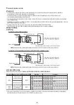
Отзывы: