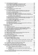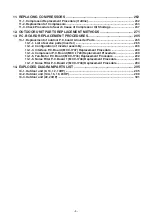
CONTENTS
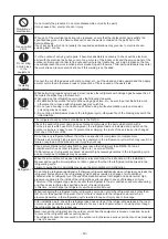
SAFETY CAUTION ....................................................................................................... 6
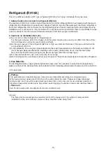
REFRIGERANT (R410A)............................................................................................
13
1. WIRING DIAGRAMS
..............................................................................................
16
2. PARTS RATING
......................................................................................................
19
2-1.
Outdoor Unit (50Hz model: MMY-MUP***1HT8
*
) ................................................
..
...........
19
2-
5
.
Inverter Assembly
..............................................................................................................
2
3
2-
6
.
Parts Layout in Outdoor Unit
............................................................................................
24
2-
7
.
Parts Layout in Inverter Assembly
...................................................................................
25
2-
8
.
Outdoor (Inverter) Print Circuit Board
.............................................................................
28
2-
8
-1.
Interface P.C. board (MCC-1747)
.............................................................................
28
2-
8
-2.
Noise Filter P.C. board (MCC-1748)
........................................................................
29
2-
8
-3.
Inverter P.C. board for compressor (MCC-1729)
...................................................
3
0
2-
8
-
4.
Inverter P.C. board for fan (MCC-1734)
..................................................................
3
1
2-
8
-5.
USB isolate P.C. board (MCC-1754)
........................................................................
3
2
3. REFRIGERANT PIPING SCHEMATIC DRAWING
................................................
3
3
4. COMBINED REFRIGERANT PIPING SYSTEM SCHEMATIC DIAGRAMS
..........
38
4-1.
Refrigerant Flow (Cooling) ................................................................................................
38
4-2.
Refrigerant Flow (Single Defrost) .....................................................................................
39
4-3.
Refrigerant Flow (Heating)
................................................................................................
4
0
4-4.
Refrigerant Flow (Individual Defrost)
..............................................................................
4
1
4-5-1.
(1) Refrigerant Flow (Automatic emergency cooling)
..........................................
4
2
4-5-2.
(1) Refrigerant Flow (Automatic emergency heating)
..........................................
44
4-6.
Refrigerant Flow (Reclaim)
...............................................................................................
46
5. CONTROL OUTLINE ..............................................................................................
47
6. APPLIED CONTROL AND FUNCTIONS
...............................................................
67
6-
6-
2
.
Test Operation of Indoor Unit
.......................
...........
..........................................................
69
6-
3
.
Method to Set Indoor Unit Function DN Code
..................
...........
....................................
7
0
6-
4.
Method to set Outdoor Unit Function Code No. (
O.
DN )
...........
........
..............
...
.
.
............
77
6-
5
.
Applied Control of Indoor Unit
......
...........
.........................................................................
82
6-
6
-1.
Outdoor Fan High Static Pressure Shift
................................................................
86
6-
6
-2.
Priority Operation Mode Setting
.............................................................................
87
6-
6
-3.
Applied Control of Outdoor Unit
............................................................................
9
0
6-
7
.
Notice Code
.......................................................................................................................
10
1
6-
8
.
System
C
ooperation
D
efrosting
......................................................................................
10
3
7. TEST OPERATION
...............................................................................................
1
08
7-1.
Procedure and Summary of Test Operation
..................................................................
1
08
7-2.
Check Items before Test Operation (before powering-on)
...........................................
1
09
7-3.
Check at Main Power-on
.................................................................................................
1
15
7-4.
Address Setup
.................................................................................................................
1
17
7-4-1.
Precautions
............................................................................................................
1
17
7-4-2.
Address Setup and Check Procedure ..................................................................
1
17
7-4-3.
Address Setup Procedure
.....................................................................................
1
18
7-4-4.
Check after Address Setup when Central Control System Is Connected
........
1
35
6-
6
.
Applied Control of
Out
door Unit
......
...........
......................................................................
86
1.
Optional Connector Specifications of Indoor P.C.Board
.................................
.
.................
67
5
-
1
.
Out
door Unit
.......................
..........
............................
.
..........................................................
47
5
-
2
.
Indoor Unit
..................
...........
.................................
..........................................................
...
56
6-
9
.
Night operation
(Sound reduction control)
..
.......
............
...........................
.....................
1
06
2-
2
.
Outdoor Unit (
6
0Hz model: MMY-MUP***1HT
7
*
) ................................................
..
...........
20
2-
3
.
Outdoor Unit (
5
0Hz model: MMY-MUP***1HT
8P-A
) ..............................................
.
..........
2
1
2-
4
.
Winding resistance of outdoor unit main parts
................................................
.
..
.
...........
2
2
- 2 -
Содержание MMY-MUP0801HT7JP
Страница 32: ...2 8 5 USB isolate P C board MCC 1754 USB communication to I F CN01 USB connector CN02 screw 32 ...
Страница 309: ......

