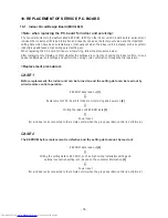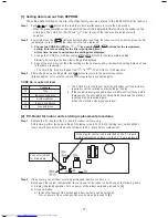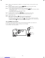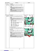
No. Part name
Procedure
Remarks
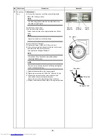
1. Detachment
1) Remove the drain hose or drain cap and then
extract the drain water accumulated in the drain pan.
2)
Remove the screws A fixing the bottom plate .
(
9
positions)
Loosen the screws B. (
4
positions)
3)
Slide the bottom plate (drain side) to the arrow
direction and then remove the panel.
4)
Loosen the screw of the drain pan supporter,
and
turn the drain pan supporter.
5)
Lower the drain pan of the drain socket side,
and remove it to the arrow direction slowly.
Drain pan
2.
Attachment
1)
Put back the drain pan, and turn back the drain pan
supporter and fix it with the screws.
2) Attach the bottom plate (drain side) to the original
position
NOTE
When removing the drain hose or drain cap, be sure
to take the drain water with a bucket, etc.
CAUTION
When removing the drain pan, do not hold the
drain socket. (Water leakage may occur.)
Bottom plate (Drain side)
Screw
B
Screw A
Drain pan
Drain pan supporter
Drain pan pull-out
direction.
Drain
socket
⑨
Sensor
TC1,TC2,TCJ
2.
Attachment
1)
Attach the TC1 sensor , TC2 sensor and TCJ sensor to
the original position.
2)
Attach the
inspection cover
as before.
3)
Attach
the wires of TC1 sensor, TC2 sensor, and TCJ
sensor as before.
4)
Attach the
electrical parts box cover
as before.
Screw
Inspection cover
Control P.C.board
MCC-1643
TCJ sensor
TC2 sensor
TC1 sensor
1.
Detachment
1)
Perform 1 of
①
to
remove
the electrical parts box
cover.
2)
Loosen the fixing screws of the inspection cover and
remove
the inspection cover.
3)
Remove the connectors of the wires of TC1 sensor ,
TC2 sensor and TCJ sensor
from the
control
P.C.board.
CN100 : TC1 sensor (3P: Brown)
CN101 : TC2 sensor (2P: Black)
CN102 : TCJ sensor (2P
:
Red)
4)
Remove the sersor from the
sensor ho
l
der
⑩
Sensor clip
Sensor holder
- 89 -


