


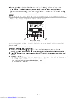


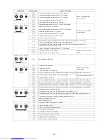


<External digital input terminal: TB2>
The following controls can be done by inputting signals to the external digital input
terminal.
▼
IN1: External
trouble
input
The air conditioner system stops and check code “L30: Indoor unit external interlock
trouble
” is displayed on the wired remote
control
when an external
trouble
is input.
▼
IN2: Prohibition of local input
is displayed on the wired remote contro
l
and operations cannot be started or
stopped from the wired remote control during prohibition of local input.
It is also possible to release local prohibition from the central remote control.
(Most recent input is given priority.)
▼
IN3: Not used
*
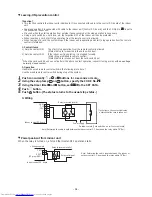
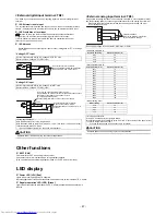
Do the wiring as shown to the right for input of either “Voltage ON: WET” or “Voltage
OFF: DRY”.
“Voltage OFF” input
“Voltage ON” input
CAUTION
Separate power lines when wiring to prevent misoperations.
Set the input switch (SW5) to the “Voltage OFF: DRY” side.
(Factory default: Voltage OFF (DRY) side)
Set the input switch (SW5) to the “Voltage ON: WET” side.
(Factory default: Voltage OFF (DRY) side)
<Wiring specifications>
Wire type: Sheathed vinyl cord, single strand
Wire thickness:
AWG14 to AWG16
(prep
0.35" to 0.4" (9 to 10mm)
of the tips of wires)
Total wire length: Max
230' (70m)
*
If you use twisted strand wires, connect a pin terminator.
COM
IN1
IN2
IN3
12 V TB2
Use contacts for micro-currents.
(Use ones that have minimum application
loads of 12 VDC and 1 mA or less.)
Input 1
Input 2
Input 3
COM
IN1
IN2
IN3
+
V
−
TB2
Use contacts for micro-currents.
(Use ones that have minimum
application loads of 12 VDC and 1 mA
or less.)
Input 1
Input 2
Input 3
Use 12 to 24 VDC for external power source.
Approximately 10 mA input current is required for each contact.
Be careful of the capacity of the power source.
(Do not apply 20
8/
2
3
0 VAC)
Connect COM terminal to + side of the power supply.
12 to 24 VDC
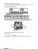
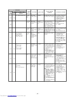
<External analog input terminal: TB3>
It is possible to change the indoor unit's operation mode (AN1), set temperature (AN2),
and blower setting (AN3) by connecting a variable resistor to the analog input terminal.
*
When both the wired remote control and the central control are used, the most
recent setting has priority.
CAUTION
Separate power lines when wiring to prevent misoperations.
Do not apply voltage or current to AN1, AN2, AN3, or COM.
<Operation mode: AN1>
Operation switching
External resistance (
Ω
)
Stop
30
Fan
60
Cool
90
Heat
120
<Set temperature: AN2>
Set temperature (°
F/°
C)
External resistance (
Ω
)
62/
17
10
64/
18
20
66/
19
30
68/
20
40
69/
21
50
71/
22
60
73/
23
70
75/
24
80
77/
25
90
78/
26
100
80/
27
110
82/
28
120
84/
29
130
86/
30
140
<Blower setting: AN3>
Blower setting
External resistance (
Ω
)
Auto
30
Fast
60
High
90
Low
120
AN1
AN2
AN3
COM
TB3
Variable resistance
Refer to the following table for the
various resistance settings.
Other functions
▼
EXCT(CN4)
Can thermo
stat
. OFF by shorting this connector.
Use contacts for micro-currents when using external contacts.
(Use ones that have minimum application loads of 12 VDC and 1 mA or less.)
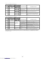
LED display
▼
Power LED (LD1) [Red]
Lights when running and power is supplied.
Normally lighted, but flashes if a transmission
trouble
occurs on the indoor unit P.C. board.
▼
Regular operation LED (LD2) [Green]
Lights when transmission with indoor unit P.C. board is established and operation is
regular.
- 47 -
<Wiring specifications>
Wire type: Sheathed vinyl cord, single strand
Wire thickness:
AWG14 to AWG16
(prep
0.35" to 0.4" (9 to 10mm)
of the tips of wires)
Total wire length: Max
230' (70m)
*
If you use twisted strand wires, connect a pin terminator.