
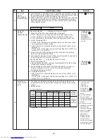


8-
5
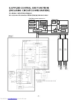
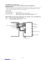
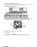
. Applied control of indoor unit
Control system using Remote location ON/OFF control box (TCB-IFCB-4
UL
)
Wiring and setting
• In the case of group control, the control system functions as long as it is connected to one of the indoor units
(control P.C. board) in the group. If it is desired to access the operation and
trouble
statuses of other units,
relevant signals must be brought to it from those units individually.
Control items
(1)
Start / Stop input signal
(2)
In-operation signa
(3)
Alarm
signal Output
Start / stop of unit
Output present while unit in normal operation
present while alarm (e.g. serial communication
trouble
or operation of
protective
device for indoor / outdoor unit) being activated
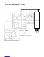
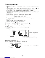
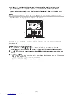
Wiring diagram of control system using
Remote location ON/OFF control box
(TCB-IFCB
-
4
UL
)
Input
Output
I
FCB-4UL: No-voltage ON / OFF serial signal
No-voltage contact (in-operation and alarm indication)
Contact capacity: Max. AC 240 V, 0.5 A
1
2
3
4
5
6
CN61
T10
(Yellow)
1
2
3
4
1
2
3
4
5
6
CN13
CN06
ON side
Start signal input
Indoor control P.C. board
TCB-IFCB
-
4UL
Start/Stop input
COM (GND)
Remote control
disabling
/ ending input
In-operation signal output
COM (+12V)
Alarm
signal output
OFF side
Stop signal input
COM
In-operation signal output
Alarm
signal output
Power supply
208/230-1-60
- 32 -