


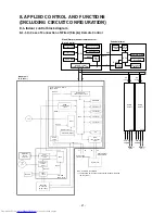


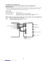

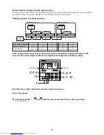


8-1-3. Connection of Both Wired (Simple) Remote Control and Wireless Remote Control
Max. 8 units are connectable.
*1
The schedule timer cannot be connected to the simple wired remote control.
Same
as left
B
A
L
1
U1U2
L2
Power
supply
Outdoor
unit
Same
as left
B
A
L
1
U1U2
L2
Power
supply
Outdoor
unit
Remote control
communication circuit
* 1
CPU
DC5V
Function setup
Key switch
Power
circuit
Display LCD
Display LED
EEPROM
CPU
DC5V
CN2
CN1
Function setup
Key switch
Display
LCD
LCD
driver
Power
circuit
Secondary
battery
Wired
(Simple)
header
remote
control
Schedule timer
#2
#3
(Follower)
(Follower)
Remote conrol
communication circuit
Remote conrol
communication circuit
MCU
EEPROM
TA sensor
TC1 sensor
TC2 sensor
TCJ sensor
HA
Driver
Start/Alarm/Ready
PMV
BUS
communication
circuit
Power
circuit
Outdoor unit
Indoor/Outdoor
communication
U1
U2
Outside output
DC12V
DC5V
DC20V
Indoor control P.C. Board
(MCC-1643)
Indoor
fan
motor
Reactor
Power
circuit
MCU
Fan motor
control
DC5V
DC15V
Fan IPDU
(MCC-1610)
Noise filter
P.C. Board
(MCC-1551)
Drain
pump
*Option
Power
circuit
Emergent
operation
SW
CPU
Buzzer
Receiving
circuit
Function
setup SW
Display
LED
DC5V
Receiving
P.C. Board
Wireless remote
control kit
Indoor
unit
#1
(Header)
A
B
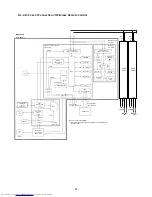
Max. 8 units are connectable.
*1 The schedule timer cannot be connected to the simple wired
remote control.
Power supply
1
Φ
208 / 230V, 60Hz
L1
L2
UART
commnucation
circuit
Application
control
P.C.Board
UART
commnucation
circuit
- 23 -
circuit