background image

AIR CONDITIONER (MULTI TYPE)

SERVICE MANUAL

Indoor unit

<

4-way cassette type

>

MMU-UP0091HP-E(TR)

MMU-UP0121HP-E(TR)

MMU-UP0151HP-E(TR)

MMU-UP0181HP-E(TR)

MMU-UP0241HP-E(TR)

MMU-UP0271HP-E(TR)

MMU-UP0301HP-E(TR)

MMU-UP0361HP-E(TR)

MMU-UP0481HP-E(TR)

MMU-UP0561HP-E(TR)

<

Ceiling type

>

MMC-UP0151HP-E(TR)

MMC-UP0181HP-E(TR)

MMC-UP0241HP-E(TR)

MMC-UP0271HP-E(TR)

MMC-UP0361HP-E(TR)

MMC-UP0481HP-E(TR)

MMC-UP0561HP-E(TR)

<

Concealed Duct Standard type

>

MMD-UP0051BHP-E

MMD-UP0071BHP-E(TR)

MMD-UP0091BHP-E(TR)

MMD-UP0121BHP-E(TR)

MMD-UP0151BHP-E(TR)

MMD-UP0181BHP-E(TR)

MMD-UP0241BHP-E(TR)

MMD-UP0271BHP-E(TR)

MMD-UP0301BHP-E(TR)

MMD-UP0361BHP-E(TR)

MMD-UP0481BHP-E(TR)

MMD-UP0561BHP-E(TR)

<

Concealed Duct High Static Pressure 

type

>

MMD-UP0

18

1HP-E

(TR)

MMD-UP0241HP-E(TR)

MMD-UP0271HP-E(TR)

MMD-UP0361HP-E(TR)

MMD-UP0481HP-E(TR)

MMD-UP0561HP-E(TR)

MMD-UP0721HP-E(TR)

MMD-UP0961HP-E(TR)

<

Concealed Duct High Static Pressure 

fresh air intake type

>

MMD-UP0481HFP-E(TR)

MMD-UP0721HFP-E(TR)

MMD-UP0961HFP-E(TR)

MMD-UP1121HFP-E(TR)

MMD-UP1281HFP-E(TR)

<

Console type

>

MML-UP0071NHP-E(TR)

MML-UP0091NHP-E(TR)

MML-UP0121NHP-E(TR)

MML-UP0151NHP-E(TR)

MML-UP0181NHP-E(TR)

<

High wall type

>

MMK-UP0031HP-E(TR)

MMK-UP0051HP-E(TR)

MMK-UP0071HP-E(TR)

MMK-UP0091HP-E(TR)

MMK-UP0121HP-E(TR)

MMK-UP0151HP-E(TR)

MMK-UP0181HP-E(TR)

MMK-UP0241HP-E(TR)

MMK-UP0031HPL-E(TR)

MMK-UP0051HPL-E(TR)

MMK-UP0071HPL-E(TR)

MMK-UP0091HPL-E(TR)

MMK-UP0121HPL-E(TR)

MMK-UP0151HPL-E(TR)

MMK-UP0181HPL-E(TR)

MMK-UP0241HPL-E(TR)

FILE NO. SVM-20095

January

, 202

1

Содержание MMC-UP0151HP-E

Страница 1: ...481BHP E TR MMD UP0561BHP E TR Concealed Duct High Static Pressure type MMD UP0181HP E TR MMD UP0241HP E TR MMD UP0271HP E TR MMD UP0361HP E TR MMD UP0481HP E TR MMD UP0561HP E TR MMD UP0721HP E TR MMD UP0961HP E TR Concealed Duct High Static Pressure fresh air intake type MMD UP0481HFP E TR MMD UP0721HFP E TR MMD UP0961HFP E TR MMD UP1121HFP E TR MMD UP1281HFP E TR Console type MML UP0071NHP E TR...

Страница 2: ...s differ in a communication type For the communication type and the model names such as each unit or remote controllers refer to the following table 78 7 2 If TU2C Link U series is combined with TCC Link other than U series the wiring specifications and the maximum number of connectable indoor units during group control operation will be changed 78 2 1 4 way cassette type 39 2 2 Ceiling type 41 2 ...

Страница 3: ... remote controller 131 9 4 Check Codes Displayed on Remote Controller and SMMS series Outdoor Unit 7 Segment Display on I F Board and Locations to Be Checked 136 9 5 Diagnostic Procedure for Each Check Code Indoor Unit 151 9 6 Sensor characteristics 159 9 7 Maintenance list 160 10 P C BOARD EXCHANGE PROCEDURES 161 10 1 Replacement of indoor P C boards 161 11 DETACHMENTS 168 12 EXPLODED VIEWS AND P...

Страница 4: ... qualified service person who is allowed to work at heights has been trained in matters relating to working at heights with the air conditioners made by Toshiba Carrier Corporation or alternatively he or she has been instructed in such matters by an individual or individuals who have been trained and is thus thoroughly acquainted with the knowledge related to this work The qualified installer is a...

Страница 5: ...uted Indicates possibilities assumed that a danger causing a death or serious injury of the repair engineers the third parties and the users due to troubles of the product after work when an incorrect work has been executed Indicates contents assumed that an injury or property damage may be caused on the repair engineers the third parties and the users due to troubles of the product after work whe...

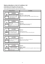
Страница 6: ...ature parts You might get burned when removing this panel CAUTION Do not touch the aluminium fins of the unit Doing so may result in injury CAUTION BURST HAZARD Open the service valves before the operation otherwise there might be the burst WARNING ELECTRICAL SHOCK HAZARD Disconnect all remote electric power supplies before servicing WARNING Moving parts Do not operate unit with grille removed Sto...

Страница 7: ... noticed that some kind of trouble such as when a check code display has appeared there is a smell of burning abnormal sounds are heard the air conditioner fails to cool or heat or water is leaking has occurred in the air conditioner do not touch the air conditioner yourself but set the circuit breaker to the OFF position and contact a qualified service person Take steps to ensure that the power w...

Страница 8: ...undertake work When working at heights use a ladder which complies with the ISO 14122 standard and follow the procedure in the ladder s instructions Also wear a helmet for use in industry as protective gear to undertake the work Before working at heights put a sign in place so that no one will approach the work location before proceeding with the work Parts and other objects may fall from above po...

Страница 9: ... of the service port is changed from one of the former R22 Do not use any refrigerant different from the one specified for complement or replacement Otherwise abnormally high pressure may be generated in the refrigeration cycle which may result in a failure or explosion of the product or an injury to your body For an air conditioner which uses R410A never use other refrigerant than R410A For an ai...

Страница 10: ...h a way that it is not slack For the installation moving reinstallation work follow to the Installation Manual If an incorrect installation is done a trouble of the refrigerating cycle water leak electric shock or fire is caused Check after repair Once the repair work has been completed check for refrigerant leaks and check the insulation resistance and water drainage Then perform a trial run to c...

Страница 11: ...to another outdoor unit Capacity overflow may occur on the terminal block and may result in fire Do not install the air conditioner in a location that may be subject to a risk of expire to a combustible gas If a combustible gas leaks and becomes concentrated around the unit a fire may occur Install the indoor unit at least 2 5 m above the floor level since otherwise the users may injure themselves...

Страница 12: ...0181HP E TR MMD UP0241HP E TR MMD UP0271HP E TR MMD UP0361HP E TR MMD UP0481HP E TR MMD UP0561HP E TR MMD UP0721HP E TR MMD UP0961HP E TR MMD UP0481HFP E TR MMD UP0721HFP E TR MMD UP0961HFP E TR MMD UP1121HFP E TR MMD UP1281HFP E TR MML UP0071NHP E TR MML UP0091NHP E TR MML UP0121NHP E TR MML UP0151NHP E TR MML UP0181NHP E TR MMK UP0031HP E TR MMK UP0051HP E TR MMK UP0071HP E TR MMK UP0091HP E TR ...

Страница 13: ...24 MMC UP0241HP E TR 30 MMC UP0271HP E TR 30 MMC UP0361HP E TR 39 MMC UP0481HP E TR 39 MMC UP0561HP E TR 39 23 MMD UP0071BHP E TR 23 MMD UP0091BHP E TR 23 MMD UP0121BHP E TR 23 MMD UP0151BHP E TR 23 MMD UP0181BHP E TR 30 MMD UP0241BHP E TR 30 MMD UP0271BHP E TR 30 MMD UP0301BHP E TR 40 MMD UP0361BHP E TR 40 MMD UP0481BHP E TR 40 MMD UP0561BHP E TR 23 MMD UP0051BHP E 34 MMD UP0181HP E TR 34 MMD UP0...

Страница 14: ...0151NHP E TR 17 MML UP0181NHP E TR 17 11 11 11 11 11 11 11 Under 70 dB 11 11 16 16 16 16 16 16 MMK UP0031HP E TR MMK UP0051HP E TR MMK UP0071HP E TR MMK UP0091HP E TR MMK UP0121HP E TR MMK UP0031HPL E TR MMK UP0051HPL E TR MMK UP0071HPL E TR MMK UP0091HPL E TR MMK UP0121HPL E TR MMK UP0151HP E TR MMK UP0181HP E TR MMK UP0241HP E TR MMK UP0151HPL E TR MMK UP0181HPL E TR MMK UP0241HPL E TR 11 MMD UP...

Страница 15: ...tor W Air filte Standard filter attached Long life filter Controller Sound pressure level H M L dBA Sound power level H M L dBA Gas side mm Liquid mm Drain port mm VP25 3 20 4 00 2 80 3 60 MMU UP0091HP E TR MMU UP0121HP E TR Starting current 0 3 0 3 Running current 0 24 0 24 Power consumption 0 021 0 021 Outer diamension Main unit 256 256 840 840 Main unit Total weight 18 18 Ceiling panel 100 5 10...

Страница 16: ...d filter attached Long life filter Controller Sound pressure level H M L dBA Sound power level H M L dBA Gas side mm Liquid mm Drain port mm VP25 100 5 100 5 840 840 256 256 840 840 Ceiling panel 9 5 9 5 100 100 Total weight Outer diamension Main unit MMU UP0181HP E TR 4 50 5 60 5 00 6 30 Electrical characteristics Running current 0 29 0 30 MMU UP0151HP E TR Power consumption 0 023 0 026 Starting ...

Страница 17: ...level H M L dBA Sound power level H M L dBA Gas side mm Liquid mm Drain port mm VP25 MMU UP0241HP E TR MMU UP0271HP E TR Appearance Ceiling panel Main unit Outer diamension Main unit MMU UP0301HP E TR 7 10 8 00 9 00 8 00 9 00 10 00 Electrical characteristics Running current 0 40 0 39 0 45 Power consumption 0 036 0 036 0 043 Starting current 0 42 0 42 0 59 256 840 840 840 840 840 840 Ceiling panel ...

Страница 18: ...H M L dBA Sound power level H M L dBA Gas side mm Liquid mm Drain port mm VP25 MMU UP0361HP E TR MMU UP0481HP E TR MMU UP0561HP E TR 11 20 14 00 16 00 12 50 16 00 18 00 Electrical characteristics Running current 0 76 0 92 0 92 Power consumption 0 088 0 112 0 112 Starting current 0 87 1 23 1 26 Appearance Main unit Ceiling panel Outer diamension Main unit 319 319 319 840 840 840 840 840 840 Ceiling...

Страница 19: ...ilte Standard filter attached Long life filter Controller Sound pressure level H M L dBA Sound power level H M L dBA Gas side mm Liquid mm Drain port mm VP25 MMC UP0151HP E TR MMC UP0181HP E TR 4 50 5 60 5 00 6 30 Power consumption 0 033 0 38 Running current 0 37 Starting current 0 55 0 034 Appearance Main unit 0 57 Electrical characteristics Ceiling panel 690 690 235 235 Ceiling panel 950 950 Mai...

Страница 20: ...d filter attached Long life filter Controller Sound pressure level H M L dBA Sound power level H M L dBA Gas side mm Liquid mm Drain port mm VP25 MMC UP0241HP E TR MMC UP0271HP E TR 7 10 8 00 8 00 9 00 Running current 0 67 0 67 Electrical characteristics Power consumption 0 067 0 067 Appearance Main unit Starting current 1 00 1 00 Ceiling panel 690 690 235 235 Outer diamension Main unit Ceiling pa...

Страница 21: ...re level H M L dBA Sound power level H M L dBA Gas side mm Liquid mm Drain port mm VP25 MMC UP0361HP E TR MMC UP0481HP E TR MMC UP0561HP E TR 11 20 14 00 16 00 12 50 16 00 18 00 Running current 0 80 0 80 1 02 Electrical characteristics Power consumption 0 083 0 083 0 111 Appearance Main unit Ceiling panel Starting current 1 20 1 20 1 43 235 235 Outer diamension Main unit 235 690 1586 1586 1586 690...

Страница 22: ...ached Long life filter Controller Sound pressure level H M L dBA Sound power level H M L dBA Gas side mm Liquid mm Drain port mm VP25 MMD UP0051BHP E MMD UP0071BHP E TR MMD UP0091BHP E TR 1 70 2 20 2 80 1 90 2 50 3 20 Power consumption 0 055 0 055 0 060 Running current 0 36 0 36 0 40 Starting current 0 56 0 56 0 60 Appearance Main unit Electrical characteristics Ceiling panel 750 750 750 700 700 7...

Страница 23: ...ter Controller Sound pressure level H M L dBA Sound power level H M L dBA Gas side mm Liquid mm Drain port mm VP25 MMD UP0121BHP E TR MMD UP0151BHP E TR MMD UP0181BHP E TR 3 60 4 50 5 60 4 00 5 00 6 30 Power consumption 0 060 0 72 0 72 Electrical characteristics Running current Starting current 0 60 0 110 0 110 Appearance Main unit 1 12 1 12 0 40 Ceiling panel 750 750 750 Main unit 275 275 275 700...

Страница 24: ...ntroller Sound pressure level H M L dBA Sound power level H M L dBA Gas side mm Liquid mm Drain port mm VP25 MMD UP0241BHP E TR MMD UP0271BHP E TR MMD UP0301BHP E TR 7 10 8 00 9 00 8 00 9 00 10 00 Running current 0 83 0 83 0 98 Electrical characteristics Power consumption 0 135 0 135 0 160 Appearance Main unit Starting current 1 23 1 23 1 38 Ceiling panel 750 750 275 275 275 750 1000 1000 1000 Out...

Страница 25: ...ller Sound pressure level H M L dBA Sound power level H M L dBA Gas side mm Liquid mm Drain port mm VP25 MMD UP0361BHP E TR MMD UP0481BHP E TR MMD UP0561BHP E TR 11 20 14 00 16 00 12 50 16 00 18 00 Running current 1 33 1 76 1 76 Electrical characteristics Power consumption 0 220 0 290 0 290 2 56 Appearance Main unit Ceiling panel Starting current 2 13 2 56 275 275 Outer diamension Main unit 275 75...

Страница 26: ...tached Long life filter Controller Sound pressure level H M L dBA Sound power level H M L dBA Gas side mm Liquid mm Drain port mm VP25 MMD UP0181HP E TR MMD UP0241HP E TR MMD UP0271HP E TR 6 30 8 00 9 00 5 60 7 10 8 00 Starting current 1 15 0 140 0 190 Power consumption 0 125 0 95 1 20 Running current 0 85 Ceiling panel Appearance Main unit 1 25 1 50 Electrical characteristics 750 750 750 298 298 ...

Страница 27: ...troller Sound pressure level H M L dBA Sound power level H M L dBA Gas side mm Liquid mm Drain port mm VP25 MMD UP0361HP E TR MMD UP0481HP E TR MMD UP0561HP E TR 12 50 16 00 18 00 11 20 14 00 16 00 Power consumption 0 230 0 300 0 400 Running current 1 43 1 86 2 57 Electrical characteristics Appearance Main unit Ceiling panel Starting current 1 93 2 46 3 17 298 298 Outer diamension Main unit 298 75...

Страница 28: ...filte Standard filter attached Long life filter Controller Sound pressure level H M L dBA Sound power level H M L dBA Gas side mm Liquid mm Drain port mm VP25 Connecting pipe 22 2 MMD UP0721HP E TR MMD UP0961HP E TR 22 40 28 00 25 00 31 50 900 1400 1400 8 15 8 15 Appearance Main unit Ceiling panel Electrical characteristics Running current 2 93 3 92 Power consumption 0 540 0 790 Starting current T...

Страница 29: ...attached Long life filter Controller Sound pressure level H M L dBA Sound power level H M L dBA Gas side mm Liquid mm Drain port mm VP25 8 90 13 90 17 40 14 00 22 40 28 00 MMD UP0481HFP E TR MMD UP0721HFP E TR MMD UP0961HFP E TR 0 90 1 12 Electrical characteristics Running current 0 80 Starting current 1 95 0 153 0 198 Power consumption 0 108 Appearance Main unit Ceiling panel 9 40 9 4 1400 1400 1...

Страница 30: ...lte Standard filter attached Long life filter Controller Sound pressure level H M L dBA Sound power level H M L dBA Gas side mm Liquid mm Drain port mm VP25 40 00 20 80 25 20 MMD UP1121HFP E TR MMD UP1281HFP E TR 33 50 Running current 1 36 1 91 Electrical characteristics 9 4 9 4 Power consumption 0 243 0 330 Appearance Main unit Ceiling panel Starting current 900 1400 1400 448 448 900 Outer diamen...

Страница 31: ...09NE WH TA09NE Sound pressure level H M L dBA Sound power level H M L dBA Gas side mm Liquid mm Drain port mm VP25 MML UP0071NHP E TR MML UP0091NHP E TR MML UP0121NHP E TR 2 50 3 20 4 00 2 20 2 80 3 60 Electrical characteristics Running current 0 20 0 20 0 23 Starting current 0 26 0 26 0 30 Power consumption 0 021 0 021 0 025 Outer diamension Main unit 600 600 600 Ceiling panel Appearance Main uni...

Страница 32: ...ed Long life filter Controller WH TA09NE WH TA09NE Sound pressure level H M L dBA Sound power level H M L dBA Gas side mm Liquid mm Drain port mm VP25 MML UP0151NHP E TR MML UP0181NHP E TR 5 00 6 30 4 50 5 60 0 42 Electrical characteristics Running current 0 29 0 55 Starting current 0 38 0 052 Power consumption 0 034 Outer diamension Ceiling panel Appearance Main unit 220 220 Main unit 600 600 Cei...

Страница 33: ...re level H M L dBA Sound power level H M L dBA Gas side mm Liquid mm Drain port mm MMK UP0031HP E TR MMK UP0051HP E TR MMK UP0071HP E TR 0 90 1 70 2 20 1 30 1 90 2 50 Electrical characteristics Running current 0 15 0 15 0 16 Starting current 0 19 0 19 0 2 Power consumption 0 013 0 013 0 015 Outer diamension Main unit 293 293 293 Ceiling panel Appearance Main unit 230 230 230 Ceiling panel 798 798 ...

Страница 34: ...NE Sound pressure level H M L dBA Sound power level H M L dBA Gas side mm Liquid mm Drain port mm MMK UP0091HP E TR MMK UP0121HP E TR MMK UP0151HP E TR 2 80 3 60 4 50 3 20 4 00 5 00 0 18 0 26 Electrical characteristics Running current 0 17 0 22 0 35 Starting current 0 21 0 017 0 028 Power consumption 0 016 Outer diamension Ceiling panel Appearance Main unit 230 230 250 Main unit 293 293 320 Ceilin...

Страница 35: ...ong life filter Controller WH TA09NE WH TA09NE Sound pressure level H M L dBA Sound power level H M L dBA Gas side mm Liquid mm Drain port mm MMK UP0181HP E TR MMK UP0241HP E TR 5 60 7 10 6 30 8 00 Ceiling panel Appearance Main unit 250 250 320 320 Total weight Fan unit 30 30 45 39 33 41 37 32 12 7 15 8 Connecting pipe 6 4 9 5 Outer diamension Main unit Ceiling panel Electrical characteristics Run...

Страница 36: ...09NE WH TA09NE Sound pressure level H M L dBA Sound power level H M L dBA Gas side mm Liquid mm Drain port mm 0 90 1 70 2 20 MMK UP0031HPL E TR MMK UP0051HPL E TR MMK UP0071HPL E TR 1 30 1 90 2 50 Electrical characteristics Running current 0 15 0 15 0 16 Power consumption 0 013 0 013 0 015 Starting current 0 19 0 19 0 2 Appearance Main unit Ceiling panel 230 230 230 293 293 293 798 798 798 Ceiling...

Страница 37: ...E Sound pressure level H M L dBA Sound power level H M L dBA Gas side mm Liquid mm Drain port mm 2 80 3 60 4 50 MMK UP0091HPL E TR MMK UP0121HPL E TR MMK UP0151HPL E TR 3 20 4 00 5 00 0 18 0 26 Electrical characteristics Running current 0 17 0 017 0 028 Power consumption 0 016 0 22 0 35 Starting current 0 21 Appearance Main unit Ceiling panel 230 230 250 Main unit 293 293 320 Outer diamension 798 ...

Страница 38: ...ng life filter Controller WH TA09NE WH TA09NE Sound pressure level H M L dBA Sound power level H M L dBA Gas side mm Liquid mm Drain port mm MMK UP0181HPL E TR MMK UP0241HPL E TR 5 60 7 10 6 30 8 00 Running current 0 29 0 42 Electrical characteristics Power consumption 0 032 0 050 Starting current 0 38 0 5 Appearance Main unit Ceiling panel 320 320 250 Outer diamension Main unit 250 1050 1050 Ceil...

Страница 39: ...Ø150 Drain pipe connecting port Meterial PP For branch duct knockout square hole Ø150 For branch duct knockout square hole Ø150 2 positions For branch duct knockout square hole Ø150 Bottom face of ceiling An obstacle Standing 850 or less 300 or less Standing 661 or less The space that is necessary for equipping and service Bottom face of ceiling Drain upstanding size 1000 or more 1000 or more 15 o...

Страница 40: ...nt pipe connecting port Ø9 5 Liquid side Refrigerant pipe connecting port Ø15 9 Gas side For branch duct knockout square hole Ø150 2 positions An obstacle Standing 850 or less 300 or less Standing 661 or less The space that is necessary for equipping and service Bottom face of ceiling Drain upstanding size 1000 or more 1000 or more 15 or more 15 or more 1000 or more Indoor unit Unit mm Knockout fo...

Страница 41: ...2 2 Ceiling type MMC UP0151HP E TR MMC UP0181HP E TR 41 ...

Страница 42: ...MMC UP0241HP E TR MMC UP0271HP E TR 6 4 12 7 42 ...

Страница 43: ...MMC UP0361HP E TR MMC UP0481HP E TR MMC UP0561HP E TR 43 ...

Страница 44: ...C D UP005 018 type 700 765 640 750 UP024 030 type E 700 180 275 750 355 345 236 22 Hanging bolt pitch 650 50 50 25 C L 570 43 187 5 131 415 113 5 Main unit dimension A Hanging bolt pitch B External dimensions of flange C Drain pan Drain pump check cover Electrical control box D 345 or more 70 or more Air discharge 100 or more 450 Check port 120 Service space E for maintenance of air filter E UP036...

Страница 45: ...37 5 37 5 27 27 960 235 2 100 100 100 100 100 100 100 100 100 100 100 254 27 27 37 5 37 5 1359 4 100 100 235 4 100 100 100 100 100 100 100 100 100 100 100 100 100 254 1375 27 27 37 5 37 5 1360 235 2 100 100 100 100 100 100 100 100 100 100 100 100 100 100 100 UP005 UP018 type Under air intake Back air intake UP024 UP030 type Under air intake Back air intake UP036 UP056 type Under air intake Back ai...

Страница 46: ...f air filter Sold separately 1000 1065 940 500 1400 1465 1340 700 650 50 50 4 Φ12 30 Hole for hanging bolt Hanging bolt mounting pitch 355 570 650 345 60 Drain pipe connecting port 170 160 180 298 750 87 255 Φ125 Knockout hole For Auxiliary fresh air flange Sold separately 131 40 100 13 22 Refrigerant pipe connecting port Liquid side Refrigerant pipe connecting port Gas side Main unit dimension A ...

Страница 47: ...00 100 100 100 13 Air inlet UP0181 UP0241 UP0271 Electrical control box 975 7 100 100 100 100 100 100 100 100 100 418 180 276 256 There are the head of the screw n 4 Make a hole at the installation of inlet duct 100 100 100 100 100 100 100 100 100 50 380 318 100 57 50 100 960 8 15 47 ...

Страница 48: ... inlet UP0361 IP0481 UP0561 Unit mm Electrical control box There are the head of the screw n 4 Make a hole at the installation of inlet duct 50 15 624 293 256 496 524 100 100 57 1360 1375 100 100 100 100 100 100 100 100 100 100 100 100 50 100 7 100 100 100 100 100 100 100 100 100 100 100 100 100 8 276 48 ...

Страница 49: ...nit more than 1000mm the service door Ceiling opening is not necessary Hole for hanging bolt 4 Φ12 30 Drain pipe connecting port Drain pump kit sold separately 850 or more Suction duct Air inlet Flexible drain hose Accessory Floor surface 200 or more 200 or more Check port Air inlet 300 or more Electrical control box 1000 or more Service space 25 Service door Ceiling opening When attached the long...

Страница 50: ...0100100100100100100 98 8 17 1296 Outside 324 84 Outside Unit mm 1316 58 200 200 200 200 200 200 58 20 44 106 44 106 44 32 200 200 200 200 200 200 361 1297 41 41 58 343 384 Air inlet 90 90 90 8 27 27 Electrical control box Air outlet 50 ...

Страница 51: ...ng Be sure to connect the flexible hose Accessory into the port Drain pipe connecting port VP25 Gravitational drainage 74 14 Dia 3 1 holes Air outlet 147 24 Refrigerant pipe connecting port Dia 9 5 Refrigerant pipe connecting port Dia 15 9 Liquid side Gas side Check port Electrical control box cover 66 76 Ceiling 100 or more 25 1450 25 2500 or more Floor surface Inspection opening Ceiling opening ...

Страница 52: ...180 Outside 178 Inside 102 327 Unit external dimension 50 50 22 20 36 44 650 Hanging bolt pitch 750 Unit external dimension Air inlet Screw holes for duct mounting 34 M5 P 13 100 1300 P 100 13 1300 50 496 295 639 539 57 13 8 7 100 100 15 256 276 65 Electrical control box 1360 1375 1 1 When attached the duct at air inlet make holes in the duct and do not interfere in it The screw head 4 places is c...

Страница 53: ...sion Take in port of wiring Electrical control box cover Air outlet P 100 11 1100 98 Air inlet 85 Connecting pipe size Model Pipe size Remarks 0721 0961 A Gas Dia22 2 B Liquid Dia12 7 1121 A Gas Dia28 6 Use the SOCKET Accessory B Liquid Dia12 7 1281 A Gas Dia28 6 Use the SOCKET Accessory B Liquid Dia15 9 Use the LIQUID JOINT PIPE Accessory Ceiling 200 or more 25 1450 25 2500 or more Floor surface ...

Страница 54: ...ectrical control box Air outlet 1430 Unit external dimension 1296 Outside Hole for hanging bolt 324 Outside 89 1465 Hanging bolt pitch 45 21 99 477 810 Hanging bolt pitch 900 Unit external dimension 74 80 Screw holes for duct mounting 26 M5 66 4 Dia12 30 Unit external dimension Air outlet P 100 11 1100 98 Air inlet 85 54 ...

Страница 55: ...121 type dia 6 35 dia 9 52 dia 12 7 dia 6 35 Drain hose Air inlet Vertical louver Upper air outlet Bottom air outlet Mounting plate Connecting pipe Gas side Dia 80mm Connecting pipe Liquid side Knock out system 45 Dia 80mm Knock out system Back body 100 70 60 100 Dia 80mm Dia 80mm Dia 80mm Dia 80mm 15 90 90 15 Mounting screw Mounting screw Mounting screw Air inlet Front View Back side View UP0151 ...

Страница 56: ...let Air Outlet 55 66 5 50 55 66 5 50 230 50 7 55 Knock Out System 50 7 55 Knock Out System Back Body Front Panel Grille Inlet 798 114 340 97 24 Installation plate hanger 131 131 140 131 120 24 Installation plate hanger Drain hose 0 4m Installation plate hanger Connecting pipe 0 35m Flare 9 52mm Connecting pipe 0 40m Flare 6 35mm 510 40 293 94 94 135 170 170 135 40 144 144 170 170 192 192 Installat...

Страница 57: ...utline Center line Hanger Hanger Outline of indoor unit For stud bold 6 For stud bold 8 10 Hanger 786 85 23 235 215 215 235 320 40 6 5 8 0 47 215 5 262 5 262 5 109 6 5 8 0 40 153 5 149 17 5 63 18 174 Wireless remote controller Remote controller holder 57 Grille Inlet Front Panel Knock Out System 50 8 73 5 Knock Out System 250 50 73 5 8 Air Filter Air Inlet Air Outlet Heat Exchanger 320 Flare 15 9 ...

Страница 58: ...3 WIRING DIAGRAMS 3 1 4 way cassette type MMU UP HP E TR 58 ...

Страница 59: ...3 2 Ceiling type MMC UP HP E TR 59 ...

Страница 60: ...3 3 Concealed Duct Standard type MMD UP BHP E TR 60 ...

Страница 61: ...3 4 Concealed Duct High Static Pressure type MMD UP HP E TR 61 ...

Страница 62: ...Concealed Duct High Static Pressure type MMD UP HP E TR 62 ...

Страница 63: ...3 5 Concealed Duct High Static Pressure fresh air intake type MMD UP HFP E TR 63 ...

Страница 64: ...IT Sold separately 5 3 2 1 4 CN521 RED OPTION HA HEAT EXCHANGER BLK 5 Indoor unit Earth screw FS unit Earth screw Stepping motor Vertical air flow louver A B TB02 Uv U2 Uv U1 OUTDOOR UNIT U1 U2 WIRED REMOTE CONTROLLER Sold separately A B M CN22 short dashed line indicate the accessories indicates the control P C board indicates the terminal block indicates the connection terminal indicates the con...

Страница 65: ...3 7 High wall type MMK UP HP E TR 65 ...

Страница 66: ...F 301 MCC 1643 MCC 1610 MCC 1551 ICF 340W250 2 MF 340W350 1 FS 1A 31 3 P C board TA sensor TC1 sensor MMC 1720 Drain pump motor Float switch Pulse motor valve PMD 08D121TF 2 Fan motor 112 Fan motor MF 340W350 3 048 128 SWF 340W1000 1 Lead wire length 218mm Dia 4 size Lead wire length 1000mm Dia 6 size Lead wire length 1000mm Dia 6 size Lead wire length 1000mm Model MMD UP HFP E TR 072 096 TC2 sens...

Страница 67: ...ooling operation 2 Controls subcool in heating operation 3 Recovers refrigerant oil in cooling operation 4 Recovers refrigerant oil in heating operation Temp Sensor Connector CN104 2P Yellow 1 Detects indoor suction temperature Functional outline TC1 Connector CN100 3P Brown 1 Controls PMV superheat in cooling operation TC2 TCJ Connector CN101 2P Black 1 Controls PMV subcool in heating operation C...

Страница 68: ... command STOP FAN COOL DRY HEAT AUTO Heat recovery system outdoor unit type Control outline Air conditioner stops Fan operation Cooling operation Dry operation Heating operation TA and Ts automatically select COOL HEAT operation mode for operation The operation is performed as shown in the following figure according to TA value at the first time only In the range of Ts 1 TA Ts 1 Cooling thermostat...

Страница 69: ...COOL HEAT is carried out as shown below When 1 5 exceeds against Tsh 10 minutes and after thermostat OFF heating operation Thermostat OFF exchanges to cooling operation Description in the parentheses shows an example of cooling ON OFF When 1 5 lowers against Tsc 10 minutes and after thermostat OFF cooling operation Thermostat OFF exchanges to heating operation 2 For the automatic capacity control ...

Страница 70: ...tion If the temperature is just on the difference boundary the fan speed does not change HEAT Value in the parentheses indicates one when sensor of the remote controller works Value without parentheses indicates one when sensor of the indoor unit sensor works If the fan speed has been changed once it is not changed for 1 minute However when the fan speed changed the fan speed changes When heating ...

Страница 71: ... HH H H H H F9 H L L L L H H H H FA L L L L L FB L L L L L L FC L L L FD LL LL LL LL LL LL LL LL LL LL LL LL LL LL CODE No 5d Type 5 Type 6 0000 0001 0002 0003 0004 0005 0006 Standard Type 1 Type 2 Type 3 Type 4 F3 H HH HH H H H H High Wall High Wall PMV less Tap Cool Dry Heat Fan Cool Dry Heat Fan Cool Dry Heat Fan Cool Dry Heat Fan Cool Dry Heat Fan Cool Dry Heat Fan Cool Dry Heat Fan F1 HH HH H...

Страница 72: ...pted and held When shifting to M zone again the timer count restarts and continues If L zone is detected the timer is cleared and the operation returns to normal operation Reset conditions 1 TC1 12 C and TC2 12 C and TCJ 12 C 2 20 minutes passed after stop P1 Q1 C a K J P2 Q2 C L N M value When the power supply is turned on the forced thermostat becomes OFF if the temperature is less than this ind...

Страница 73: ...e drain pump 2 During operation of the drain pump if the float switch operates the drain pump continuously operates and a check code is issued 3 During stop status of the drain pump if the float switch operates the thermostat is forcedly off and this control operates the drain pump After continuous operation of the float switch for approx 5 minutes this control stops the operation and a check code...

Страница 74: ...r HEAT READY display Operation possible Operation impossible Selection of central control mode 18 Operation from central controller Individual Central 1 Central 2 Central 3 Central 4 Operation on remote controller ON OFF Operation Timer Temp Fan speed Air direction setting selection setting setting setting setting Display of filter sign Not provided to the wireless type 1 The filter sign is displa...

Страница 75: ...t or the locked louver closes fully when the unit stops and the louver is automatically set to horizontal discharge position when PRE HEAT Heating ready is displayed heating thermo is off Individual air direction setup 02 E E b box ox 04 Refrigerant pipe Drain pipe 01 03 Pushing UNIT LOUVER Louver select button enables every discharge port to set up the air direction The louver numbers that are di...

Страница 76: ...set by the setup data of Item code DN F0 In case of selecting the Swing mode Dual swing or Cycle swing the following numerals is displayed at the center of the remote controller screen for approx 3 seconds when SWING FIX button was pushed to select SWING No display for the standard swing Remarks Carry out setting operation during stop of the unit otherwise the unit stops operation Dual swing Cycle...

Страница 77: ...ler screen 20 DC motor 1 When the fan starts positioning is performed for the starter and the rotor Vibrate slightly 2 DC motor operates according to the command from the indoor controller Note If the fan rotates by entry of outside air etc while the air conditioner stopped the indoor unit may operate as the fan motor stops Note If the fan lock was detected the operation of the indoor unit stops a...

Страница 78: ...ies and future models TCC Link Other than U series Outdoor unit MMY MUP This letter indicates U series model Other than U series MMY MAP MCY MHP Indoor unit MM UP This letter indicates U series model Other than U series MM AP Wired remote controller RBC A U This letter indicates U series model Other than U series Remote sensor TCB TC U This letter indicates U series model Other than U series Wirel...

Страница 79: ...r unit 1 Header PMV Louver motor Indoor fan motor CPU DC5V DC5V 1 CN2 CN1 Wired remote controller Up to 2 units Schedule timer Function setup LCD driver CPU Power circuit EEPROM TA sensor TC1 sensor TC2 sensor TCJ sensor HA Application control kit Occupancy sensor Outdoor unit Fan motor control circuit Start Alarm BUS communication circuit Power circuit Power circuit Remote controller communicatio...

Страница 80: ...nication circuit MCU EEPROM TA sensor TC1 sensor TC2 sensor TCJ sensor HA Application control kit Occupancy sensor Driver Remote controller communication circuit Remote controller communication circuit DC 280V Indoor unit 1 Header Indoor fan motor Power supply 220 240V 50Hz 208 230V 60Hz Power supply Power supply Indoor Outdoor communication Outdoor unit 2 3 Follower Follower L N PMV Louver motor ...

Страница 81: ...Alarm BUS communication circuit MCU EEPROM TA sensor TC1 sensor TC2 sensor TCJ sensor HA Wireless kit Application control kit Driver Remote controller communication circuit DC 280V Indoor unit 1 Header Indoor fan motor Uv U1 Uv U2 Uv U1 Uv U2 Power supply 220 240V 50Hz 208 230V 60Hz Power supply Power supply Indoor Outdoor communication Outdoor unit 2 3 Follower Follower L N PMV Louver motor Drain...

Страница 82: ...le timer LCD driver Power circuit EEPROM TA sensor TC1 sensor TC2 sensor TCJ sensor HA Wireless Occupancy sensor Application control kit Outdoor unit Fan motor control circuit Start Alarm BUS communication circuit Power circuit Power circuit Remote controller communication circuit Remote controller communication circuit Display LCD Display LCD Display LED EEPROM Secondary battery Key switch Key sw...

Страница 83: ...Display LCD Function setup Key switch CN2 CN1 1 Display LED Display LCD LCD driver CPU Remote controller communication circuit Function setup Key switch Power circuit Power circuit DC280V Fan motor control circuit MCU EEPROM1 EEPROM2 TA sensor TC1 sensor TCJ sensor Float input HA Bus communication circuit AC synchronous signal input circuit Power circuit Secondary battery Outdoor unit CPU TC2 sens...

Страница 84: ...ller communication circuit Power circuit DC280V Fan motor control circuit MCU EEPROM1 EEPROM2 TA sensor TC1 sensor TCJ sensor Float input HA Bus communication circuit AC synchronous signal input circuit Outdoor unit TC2 sensor Power supply 220 240V 50Hz 208 230V 60Hz Power Supply Power Supply Uv U1 Uv U2 Outdoor Unit Max 8 or 16 units are connectable depending on connection system 1 The schedule t...

Страница 85: ...ion setup Key switch CN2 CN1 1 Display LED Display LCD LCD driver CPU Remote controller communication circuit Function setup Key switch Power circuit Power circuit DC280V Fan motor control circuit MCU EEPROM1 EEPROM2 TA sensor TC1 sensor TCJ sensor Float input HA Bus communication circuit AC synchronous signal input circuit Power circuit Secondary battery Outdoor unit CPU TC2 sensor Power supply 2...

Страница 86: ...river CPU Central control communication circuit Remote controller communication circuit Display LED Receiver unit Driver Function setup Key switch Power circuit Power circuit DC280V DC15V Fan motor control circuit EEPROM TA sensor TC1 TC2 sensor TCJ sensor HA Run Alarm Ready Thermo ON COOL HEAT FAN Wireless remote signal setting A B Central control remote controller Sold separately AC synchronous ...

Страница 87: ...DC20V Outside output Central control communication circuit Remote controller communication circuit Display LED Receiver unit Driver Power circuit DC280V DC15V Fan motor control circuit EEPROM TA sensor TC sensor TCJ sensor HA Run Warning Defrost Thermo ON COOL HEAT FAN Bus communication circuit Wireless remote signal setting A B Central control remote controller Sold separately AC synchronous sign...

Страница 88: ... TC2 sensor CN101 Black Drain pump CN504 White TA sensor CN104 Yellow Not use CN20 Blue Function switching J01 Function switching J08 Application control kit CN521 Red Remote controller communication LED D504 Green Indoor Outdoor central control communication LED D503 Yellow PMV output CN82 Blue HA T10 CN61 Yellow Wireless remote control CN214 White DC fan motor CN210 White Option power supply CN3...

Страница 89: ... controller DN 31 ON OFF input 0V㧔COM㧕 Remote controller prohibited input Operation output Open collector DC12V㧔COM Warning output Open collector HA ON OFF input J01 YES NO Pulse At shipment from factory Static input selection Permission Prohibition of remote controller operation stop is performed by input Operation ON Answer back of HA Warning output ON Check mode input 0V This check is used to c...

Страница 90: ...sor CN100 Brown TCJ Sensor CN102 Red TF Sensor CN103 Green TCJ Sensor CN104 Yellow EEPROM IC503 Ventilation output CN32 White Application control kit CN521 Red HA T10 CN61 Yellow DISP CN72 White CHK CN71 White Indoor Outdoor communication CN40 Blue Remote controller CN41 Blue Option power supply CN309 Yellow Power supply CN67 Black Reactor CN01 Blue CN82 Blue 90 ...

Страница 91: ...pen collector DC12V㧔COM Warning output Open collector HA ON OFF input J01 YES NO Pulse At shipment from factory Static input selection Permission Prohibition of remote controller operation stop is performed by input Operation ON Answer back of HA Warning output ON Check mode input 0V This check is used to check indoor operation Performs operation of indoor fan H Louver horizontal and Drain pump ON...

Страница 92: ...or CN104 White TC2 Sensor CN101 Black Float SW CN34 Red TC1 Sensor CN100 Brown DISP N72 White CHK CN71 White EEPROM IC503 Option power supply CN309 Yellow Power supply CN67 Black DC fan motor CN210 White Louver CN33 White PMV Output CN82 Blue Output FS Unit CN81 Black Ventilation output CN32 White HA T10 CN61 Yellow High Wall type Console type 92 ...

Страница 93: ...COM㧕 Remote controller prohibited input Operation output Open collector DC12V㧔COM Warning output Open collector HA ON OFF input J01 YES NO Pulse At shipment from factory Static input selection Permission Prohibition of remote controller operation stop is performed by input Operation ON Answer back of HA Warning output ON Check mode input 0V This check is used to check indoor operation Performs ope...

Страница 94: ...tton Change the mode from COOL to HEAT using MODE button Do not use MODE button for other mode except COOL HEAT modes The temperature cannot be adjusted during test run The trouble detection is performed as usual After test run push ON OFF button to stop the operation Display on the display part is same to that in Procedure 1 Push TEST button to clear the TEST mode TEST display in the display part...

Страница 95: ...ay part and the test run is permitted 2 Push ON OFF button 3 Push menu button to select the operation mode Select Cool or Heat with setting button Do not run the air conditioner in a mode other than Cool or Heat The temperature setting function does not work during test run The check code is displayed as usual 4 After the test run push OFF timer button to stop a test run TEST disappears on the dis...

Страница 96: ...ns After confirming a signal receiving sound beep immediately set the temperature to 29 C with the temp setup buttons Cooling test run Heating test run After confirming a signal receiving sound beep immediately set the temperature to 17 C with the temp setup buttons After confirming a signal receiving sound beep immediately set the temperature to 30 C with the temp setup buttons 4 5 6 Repeat proce...

Страница 97: ...tion to short circuit of CHK pin CN71 on the indoor P C board the minimum opening degree 30 pls can be set to the indoor PMV only When open DISP pin the maximum opening degree 1500 pls can be obtained again For the detailed positions of CHK pin CN71 on indoor P C board and DISP pin CN72 on indoor P C board refer to the indoor P C board How to clear Open CHK pin While the system is operating it sto...

Страница 98: ...unction 5 Push the button The display changes from flashing to steady To change the selected indoor unit go back to step 2 To change the selected function go back to step 3 6 When the button is pushed the system returns to normal off state TEMP ON OFF SET TIME TEST FILTER RESET CL SAVE SWING FIX VENT UNIT LOUVER CODE No UNIT No R C No TIMER SET MODE FAN SETDATA TEST SETTING 00 01 1 1 10 5 4 1 2 6 ...

Страница 99: ...e selected indoor unit repeat from Procedure 4 7 When all the settings have been completed push ON OFF button to finish the settings Return to the normal mode SETTING flashes and then the display content disappears and the air conditioner enters the normal stop mode The remote controller is unavailable while SETTING is flashing To change settings of another indoor unit repeat from Procedure 1 3 Pu...

Страница 100: ...t to 0064 No 30 unit TCC LINK 00Un 0099 Unfixed 1 0001 No 1 unit to 0128 No 128 unit TU2C LINK 00Un Unfixed When using U series remote controller 0099 Unfixed Other than U series remote controller Indoor unit address 0001 No 1 unit to 0064 No 64 unit TCC LINK 00Un 0099 Unfixed 1 0001 No 1 unit to 0128 No 128 unit TU2C LINK 00Un Unfixed When using U series remote controller 0099 Unfixed Other than ...

Страница 101: ...swing 0003 Cycle swing Louver fixed position 0000 Release 0001 Horizontal discharge position 0000 Not fixed Louver No 1 0005 Downward discharge position Louver fixed position 0000 Release 0001 Horizontal discharge position 0000 Not fixed Louver No 2 0005 Downward discharge position Louver fixed position 0000 Release 0001 Horizontal discharge position 0000 Not fixed Louver No 3 0005 Downward discha...

Страница 102: ...ller use is impossible 0000 No central device control 103 Remote controller 0000䋺Use 0001䋺Do not use 0000㧦Use 1 Display order of 00Un and 0099 varies depending on remote controller models or communication types 2 Communication protocol can be automatically switched with the setup in the outdoor unit during installation For Central control address DN 03 Indoor unit address DN 13 FS unit address DN ...

Страница 103: ... 0006 100 Pa 50 Pa 75 Pa 150 Pa 125 Pa 175 Pa 200 Pa Concealed Duct High static pressure type UP0181 0561 Series 0000 0001 0002 0003 0004 0005 0006 100 Pa 50 Pa 75 Pa 150 Pa 125 Pa 175 Pa 200 Pa UP0721 0961 Series 0000 0001 0002 0003 0004 0005 0006 150 Pa 50 Pa 83 Pa 217 Pa 117 Pa 183 Pa 250 Pa Set data External static pressure Factory default Set data External static pressure Factory default Set ...

Страница 104: ...241 271 301 361 481 561 08 High Wall MMK UP0031 051 071 091 121 151 181 241 07 Ceiling MMC UP0151 181 241 271 361 481 561 18 Console MML UP0071 091 121 151 181 16 Concealed Duct High static pressure MMD UP0481 721 961 1121 1281 Fresh Air Intake type Value Capacity 41 0051 01 0071 03 0091 05 0121 07 0151 09 0181 11 0241 12 0271 13 0301 15 0361 17 0481 18 0561 21 0721 23 0961 24 1121 25 1281 Indoor ...

Страница 105: ...eration 3 Check code Output present while alarm e g serial communication trouble or operation of protective device for indoor outdoor unit being activated 2 Wiring diagram of control system using Remote location ON OFF control box TCB IFCB 4E2 Input IFCB 4E2 No voltage ON OFF serial signal Output No voltage contact in operation and check code indication Contact capacity Max AC 240 V 0 5 A 1 2 3 4 ...

Страница 106: ...the selected indoor unit turns on 2 Every pushing UNIT LOUVER button left side of the button the indoor unit numbers in group control are displayed successively In this time the fan of the selected indoor unit only turns on 3 Using the setup temp or button specify the CODE No 31 4 Using the timer time or button select the SET DATA At shipment 0000 The setup data are as follows 5 Push button OK if ...

Страница 107: ...Connecting to the CN61 connector NOTE Determine the cable length between the indoor control P C board and the relay within 3m Indoor control P C board 1 2 1 2 CN4 EXCT RED In the figure the contact indicates a status that the card is taken out Power supply Outside contact Card switch box etc Procured locally Relay procured locally Connecting to the Application control kit TCB PCUC2E connector CN4 ...

Страница 108: ... operation even the previous mode is off operation See contents below for DN settings and detailed operations Card Input 5 1 To change a setting temperature fan speed and wind direction by changing data at DN code No 16C to 171 2 The operation mode can be set by changing data 0000 0001 at DN code No 16A 0000 operation mode is the same at the current mode factory setting default 0001 operation auto...

Страница 109: ... to 24ºC and 24ºC respectively due to change in code No 172 173 The operation mode continues running at the same as the current mode The setting temperature of cooling dry and heating mode is changed to 27ºC and 20ºC respectively due to change in code no 172 173 The fan speed for all operation modes is changed due to change in code no 16F The wind direction of Cooling dry fan and heating mode are ...

Страница 110: ...d Relay procured locally Relay supply 1 2 1 2 Signal input at contact point in drawings is in OFF state External device filter clogged signal etc External device filter clogged signal etc Connecting to the Application control kit TCB PCUC2E connector CN4 CN4 EXCT RED Application control kit Relay procured locally Relay supply Note Determine the cable length between the indoor control P C board and...

Страница 111: ... for more than 4 seconds LCD starts flashing Outdoor unit Remote controller Indoor unit 1 Refrigerant line 1 Refrigerant line 2 Indoor unit 2 Indoor unit 3 Outdoor unit Indoor unit 1 Indoor unit 2 1 Line system address 1 1 2 2 1 Indoor unit address 2 3 1 2 1 Header unit Group address 2 Follower unit 2 Follower unit 2 Follower unit 2 Follower unit Code No SET DATA 1 3 6 9 11 2 5 8 4 7 10 SET TIME T...

Страница 112: ... 0002 0002 Individual 0000 Header unit 0001 Follower unit 0002 10 Push the button It is OK if the display turns on 11 Push the button The address setting is complete SETTING flashes You can control the unit after SETTING has disappeared In case of group control RBC ASCU11 2 3 4 3 4 3 4 6 2 5 1 Push and hold the menu buttons at same time for more than 10 seconds 2 Push the OFF timer button to confi...

Страница 113: ...n the header outdoor unit interface P C board the lowest system address number After finishing all the settings above set the address of the central control devices For the setting of the central control address refer to the installation manual of the central control devices In the case of combining with outdoor units other than Super Modular Multi System u series SMMS u Set a system address for t...

Страница 114: ...utton if the units stop 2 Push the UNIT LOUVER button left side of the button A unit numbers 1 1 1 1 1 1 1 1 1 1 is indicated on the LCD it will disappear after a few seconds The indicated number shows the system address and indoor unit address of the unit When 2 or more indoor units are connected to the remote controller group controlled units a number of other connected units appears each time y...

Страница 115: ...indicated one after another The first indicated unit number is the address of the header unit Only the fan and louvers of the indicated indoor unit are activated 3 Push the button to finish the procedure All the indoor units in the group stop 1 2 3 Stop 1 SET TIME TIMER SET TEST FILTER RESET TEMP CL FAN SAVE SWING FIX VENT MODE ON OFF UNIT LOUVER RBC ASCU11 1 Push and hold the menu buttons at same...

Страница 116: ... LOUVER button left side of the button and SWING FIX buttons repeatedly to select a system address 3 Push the button to confirm the system address selection The address of an indoor unit connected to the selected refrigerant line is indicated on the LCD display and its fan and louvers are activated 4 Push the UNIT LOUVER button left side of the button Each time you push the button the indoor unit ...

Страница 117: ...UNIT No is that of the head unit 2 Push the UNIT LOUVER button left side of the button repeatedly to select an indoor unit number to change if 2 or more units are controlled in a group The fan and louvers of the selected indoor unit are activated The fan of the selected indoor unit is turned on 3 Push the TEMP buttons repeatedly to select13 13 13 13 13 for CODE No 4 Push the TIME buttons repeatedl...

Страница 118: ...he menu button until the CODE No flashes And using the or buttons specify the CODE No 13 4 Push the menu button until the SET DATA flashes And using the or buttons set an indoor unit address 5 Push the OFF timer button to confirm the SET DATA 6 When all the settings have been completed push the ON OFF button return to normal mode 2 3 4 3 4 2 5 1 6 3 4 118 ...

Страница 119: ...ne is indicated on the LCD display and the fan and louvers of the unit are activated At first the current indoor unit address is displayed in SET DATA No system address is indicated 4 Push the TIME buttons repeatedly to change the value of the indoor unit address in SET DATA Change the value in SET DATA to that of a new address 5 Push the button to confirm the new address on SET DATA 6 Push the UN...

Страница 120: ...n A of the following figure counts down as follows at 5 second intervals 0005 0005 0005 0005 0005 o o o o o 0004 0004 0004 0004 0004 o o o o o 0003 0003 0003 0003 0003 o o o o o 0002 0002 0002 0002 0002 o o o o o 0001 0001 0001 0001 0001 o o o o o 0000 0000 0000 0000 0000 The check code is cleared when 0000 0000 0000 0000 0000 appears However the display counts down from 0005 0005 0005 0005 0005 a...

Страница 121: ...ODE No to FF FF FF FF FF 5 The display in A of the following figure counts down as follows at 5 second intervals 0005 0005 0005 0005 0005 o o o o o 0004 0004 0004 0004 0004 o o o o o 0003 0003 0003 0003 0003 o o o o o 0002 0002 0002 0002 0002 o o o o o 0001 0001 0001 0001 0001 o o o o o 0000 0000 0000 0000 0000 The check code is cleared when 000 appears However the display counts down from 005 aga...

Страница 122: ...he next page for CODE No 3 Push the left part of the UNIT LOUVER button left side of the button to change to the item to monitor Monitor the sensor temperature or operation status of the indoor unit and outdoor unit in the refrigerant line 4 Push the button to return the display to normal RBC ASCU11 1 2 4 2 4 5 3 1 Monitoring function display Indoor unit number Data 1 Push the menu button for over...

Страница 123: ...outdoor unit for outdoor service monitor list 1 C 01 Room temperature Remote controller 1 C C 1 Indoor suction air temperature TA 02 C 1 Indoor coil temperature TCJ 03 C 1 Indoor coil temperature TC2 04 C 1 Indoor coil temperature TC1 05 06 Indoor discharge air temperature TF 1 C 0150 1500pls pls 1 10 Indoor PMV opening 08 07 Indoor fan motor number of revolutions 0600 600rpm 1 rpm 㷄 㷄 F9 Suction ...

Страница 124: ...e l b i s s o P r o i v a h e B O N 1 A compressor would not start The air conditioner is being controlled by the 3 minute protective function It is in standby status though the room temperature has reached the setup temperature It is being operated in timer mode or fan mode It is being in initial communication 2 An indoor fan would not start The air conditioner is being controlled by the cool air...

Страница 125: ...s been open short circuit F03 ALT Indoor heat exchanger temperature sensor TC1 check code Heat exchanger temperature sensor TC1 has been open short circuit F10 ALT Ambient temperature Ambient temperature sensor TA has been open short circuit sensor TA check code F11 ALT Discharge temperature sensor TF check code Discharge temperature sensor TF has been open short circuit F29 SIM Indoor EEPROM is a...

Страница 126: ...pose device control interface Device connected to general purpose device control interface is trouble P30 L20 L20 is displayed Communication Link Duplication addresses of indoor units in central control device With the combination of air conditioning system the indoor unit may detect the check code of L20 Operation Timer Ready Check code detected by central control device Note The same trouble e g...

Страница 127: ... of outdoor unit from which signal is not received normally E26 Signal lack of outdoor unit Follower outdoor unit initially communicating normally fails to do so reduction in number of follower outdoor units connected Outdoor follower unit trouble E28 E28 O Detected outdoor unit No utdoor header unit detects trouble relating to follower outdoor unit detail displayed on follower outdoor unit E31 E3...

Страница 128: ...D2 wiring trouble Wiring installation trouble or detachment of outdoor discharge temperature sensor TD2 has been detected H16 01 TK1 oil circuit trouble 02 TK2 oil circuit trouble H16 Oil level detection circuit trouble No temperature change is detected by temperature sensor for oil level detection TK1 TK2 despite compressor having been started L04 L04 SIM SIM SIM L05 L06 Duplicated outdoor refrig...

Страница 129: ...ue to detection of overflow detected by indoor unit P13 P13 ALT Outdoor liquid backflow detection trouble State of refrigerant cycle circuit indicates liquid backflow operation P15 P15 ALT 01 TS condition Indoor unit overflow Gas leak detection 02 TD condition Outdoor suction temperature sensor TS1 detects sustained and repeated high temperatures that exceed standard value P17 Outdoor discharge TD...

Страница 130: ...s detected while inverter compressor is turned off P04 01 Compressor 1 02 Compressor 2 ALT Activation of high pressure SW High pressure SW is activated P04 P22 ALT P22 Compressor breakdown Outdoor fan P C board trouble 1 Fan P C board 1 2 Fan P C board 2 Outdoor fan P C board detects trouble P26 1 Compressor 1 2 Compressor 2 Activation of IPM compressor short circuit protection Short circuit prote...

Страница 131: ...ory access procedure is described below up to four check codes stored in memory Check code history can be accessed regardless of whether the air conditioner is in operation or shut down Procedure To be performed when system at rest 1 Invoke the SERVICE CHECK mode by pressing the buttons simultaneously and holding for at least 4 seconds The letters SERVICE CHECK light up and the check code 01 is di...

Страница 132: ...occurred 2 Each time the setting button is pushed the recorded troubleshooting history is displayed in sequence The troubleshooting history appears in order from 01 newest to 04 oldest CAUTION CAUTION In the troubleshooting history mode DO NOT push the Menu button for over 10 seconds doing so deletes the entire troubleshooting history of the indoor unit 3 After you have finished checking push the ...

Страница 133: ...erflow trouble P12 Indoor DC fan trouble P13 Outdoor liquid backflow detection trouble P03 Outdoor discharge TD1 temperature trouble P04 Activation of outdoor high pressure SW P05 Open phase power failure Inverter DC voltage Vdc trouble MG CTT trouble P07 Outdoor heat sink overheating trouble Poor cooling of electrical component IGBT of outdoor unit P15 Gas leak detection insufficient refrigerant ...

Страница 134: ...l H08 Trouble in temperature sensor for oil level detection circuit TK1 TK2 TK3 TK4 or TK5 H15 Wiring installation trouble or detachment of outdoor discharge temperature sensor TD2 H16 Oil level detection circuit trouble Trouble in outdoor unit TK1 TK2 TK3 TK4 or TK5 circuit H25 Wiring installation trouble or detachment of outdoor discharge temperature sensor TD3 L03 Duplicated indoor group header...

Страница 135: ...tion Timer Synchronized blinking Ready Alternate blinking Operation Timer Ready Light block Check code Cause of trouble Communication trouble between indoor unit s and FS unit s FS unit s system trouble Operation Timer Blinking Ready Synchronized blinking Operation Timer Ready Duplicated FS units E17 L12 FS unit s setting trouble L24 J03 FS unit overflow trouble J10 FS unit temperature sensor TCS ...

Страница 136: ...ss or network adaptor E03 Check order in which power was turned on for indoor and outdoor units Check indoor address setting Check indoor outdoor tie cable Check outdoor terminator resistor setting SW100 Bit 2 Indoor unit Indoor outdoor communication circuit trouble detected at indoor end Stop of corresponding unit Indoor unit is not receiving signal from outdoor unit E04 Check power supply to ind...

Страница 137: ... Check for any change made to remote controller connection group individual since indoor address setting Indoor unit I F Duplicated indoor address Duplicated indoor address All stop More than one indoor unit are assigned same address E08 E08 Check remote controller settings Check remote controller P C boards Remote controller Duplicated master remote controller Stop of corresponding unit In two re...

Страница 138: ...its in one line There is no outdoor header unit in one line E19 E19 Disconnect inter line tie cable in accordance with automatic address setting method explained in Address setting section I F 01 Connection of outdoor unit from other line 02 Connection of indoor unit from other line Connection to other line found during automatic address setting All stop Equipment from other line is found to have ...

Страница 139: ...ation trouble between MCU and Sub MCU All stop Communication between MCU and Sub MCU stopped 80 Check connection of TCJ sensor connector and wiring Check resistance characteristics of TCJ sensor Check for failure in indoor P C board Indoor TCJ sensor trouble Indoor unit Stop of corresponding unit Sensor resistance is infinity or zero open short circuit F01 Check connection of TC2 sensor connector ...

Страница 140: ...ace Compressor P C board TH sensor trouble Compressor P C board 1 Compressor 1 side 2 Compressor 2 side All stop Sensor resistance is infinity or zero open short circuit F13 F13 Check connection of TO sensor connector Check resistance characteristics of TO sensor Check for failure in outdoor P C board I F TO sensor trouble I F All stop Sensor resistance is infinity or zero open short circuit F08 F...

Страница 141: ...ssor 2 side All stop Inverter current detection circuit detects overcurrent and shuts system down H01 H01 Check current detection circuit wiring Check failure in outdoor P C board Compressor Current detection circuit trouble Compressor P C board 1 Compressor 1 side 2 Compressor 2 side All stop Current flow of at least specified magnitude is detected despite inverter compressor having been shut tur...

Страница 142: ...door P C board I F TD2 sensor miswiring incomplete insertion I F All stop Discharge temperature of TD2 does not increase despite compressor 2 being in operation H15 H15 Check connection of TK2 sensor connector Check resistance characteristics of TK2 sensor Check for failure in outdoor P C board I F All stop Sensor resistance is infinity or zero open short circuit Main remote controller Outdoor 7 s...

Страница 143: ...d on indoor unit other than priority indoor unit I F No of priority indoor units All stop More than one indoor units have been set up as priority indoor unit L06 L06 Check indoor addresses Connection of group control cable to standalone indoor unit Indoor unit Stop of corresponding unit There is at least one standalone indoor unit to which group control cable is connected L07 Check indoor addresse...

Страница 144: ...oor fan motor trouble Indoor unit Stop of corresponding unit P01 Check outdoor service valves gas side liquid side to confirm full opening Check outdoor PMVs PMV1 2 3 4 for clogging Check resistance characteristics of TD1 sensor Check for insufficiency in refrigerant quantity Check for failure in 4 way valve Check for leakage of SV4 circuit Check SV4 circuit wiring or installation trouble in SV41 ...

Страница 145: ...TH Check shortage of refrigerant Check outdoor service valves Check connection of TL2 sensor Check resistance characteristics of TL2 sensor Check resistance characteristics of TO sensor Check malfunctions of Pd and Ps sensors Check outdoor I F P C board malfunction Check PMV2 and PMV3 Heat sink overheating trouble Heat sink dew condensation trouble 01 Compressor 1 heat sink trouble 02 Compressor 2...

Страница 146: ...g Check resistance characteristics of TD1 and TD2 sensors Check indoor filter for clogging Check piping for clogging Check SV4 circuit for leakage or coil installation trouble Gas leak detection TD condition I F 02 TD condition All stop Protective shutdown due to sustained discharge temperature TD1 or TD2 at or above 108 C for at least 10 minutes is repeated four times or more Check float switch c...

Страница 147: ...eration Pd sensor detects pressure equal to or greater than 3 85 MPa During heating operation Pd sensor detects pressure equal to or greater than 3 6 MPa P20 P20 Main remote controller Outdoor 7 segment display Check code Sub code Check outdoor service valves gas side liquid side to confirm full opening Check outdoor PMVs PMV1 2 3 4 for clogging Check resistance characteristics of TD2 sensor Check...

Страница 148: ...ector connection Check for compressor layer short circuit Check for failure in compressor P C board Compressor position detection circuit trouble Compressor P C board 1 Compressor 1 side 2 Compressor 2 side All stop Position detection is not going on normally P29 P29 Check indoor P C board Other indoor trouble group follower unit trouble Indoor unit Stop of corresponding unit There is trouble in o...

Страница 149: ...P C boards of devices at other end of central control communication line Central control device reception trouble Central control device Continued operation Central control device is unable to receive signal C06 Check trouble input Batch alarm for general purpose device control interface General purpose device I F Continued operation Trouble signal is input to control interface for general purpose...

Страница 150: ... the power supply 2 Remove compressor leads from the compressor P C board Be sure to remove all the leads 3 With each compressor check the phase to phase winding resistances and winding to outdoor cabinet resistance using a multimeter Earth trouble o It is normal if the winding to outdoor cabinet resistance is 10M or more Inter winding short circuit o It is normal if the phase to phase resistances...

Страница 151: ...in Replace indoor P C board Replace remote controller Change one to header other to follower Remote controller address connector Check code Check code name Cause Check code Check code name Cause The check code is not indicated on the central control device or the 7 segment indication on the outdoor unit Yes No E02 E03 Signal transmission trouble on the remote controller Communication trouble betwe...

Страница 152: ... etc Turn on power again in order of indoor unit outdoor unit Correct inter unit wire Check connection of inter unit wire between indoor and outdoor is correct and then connect communication line connector on indoor P C board CN40 to CN44 EMG Correct the terminator resistor setup Set up address again Replace the fuse Check noise etc and eliminate it if any Replace indoor P C board Yes Yes No No Ye...

Страница 153: ...tion trouble between Application control kit and Indoor unit 1 Application control kit trouble 2 Indoor P C board trouble Is the connection for the UART communication connector indoor P C board CN521 red Application control kit CN1 red normal YES NO Is connector lead wire for the UART communication cut Does Red LED LD1 on the Application control kit light up Red LED LD1 on the Application control ...

Страница 154: ...Replace indoor interface P C board Yes No Yes No F01 Yes No Yes No F02 Check code Check code name Cause Check code Check code name Cause Indoor TCJ sensor trouble TCJ sensor Open Short circuit Indoor TC2 sensor trouble TC2 sensor Open Short circuit Is TCJ sensor connector CN102 Red on indoor P C board normally connected Are characteristics of TCJ sensor resistance value normal Is TC2 sensor connec...

Страница 155: ... Power ON Repetition Approx 3 minutes Approx 1 minute Indoor other trouble Indoor P C board trouble This trouble is detected during operation of air conditioner of IC10 non volatile memory EEPROM on indoor unit P C board Replace service P C board If EEPROM was not inserted when power was turned on or it is absolutely impossible to read write EEPROM data the automatic address mode is repeated SET D...

Страница 156: ... a group during group control L08 Yes No Check code Cause Indoor unit address is unset Check code name Indoor group address unset Are powers of all the indoor units turned on Turn on the power of indoor units Turn on the power of outdoor unit again Re execute address setup Refer to Address setup Clear addresses Refer to Address clear Note This code is displayed when the power is turned on at the f...

Страница 157: ...ltage of 1 3 pin of CN504 on indoor P C board P10 Sub code Overflowing indoor unit s address Cause Check code Is float SW connector Indoor control P C board CN34 connected normally Does float SW operate Is wiring normal Does drain pump operate Is there a trap in the drainage route Is power supply to drain pump normal Correct connector connection Check and correct wiring Check indoor P C board Fail...

Страница 158: ...or R05 of the indoor P C board normal Pin No 7 Color Blue Yellow White Black Red Measure by connecting the com side to 4 Black while measuring The measurement may vary Measurement place Resistance value a b c I Between 4 Black 1 Red MΩ II Between 4 Black 5 White 35k 65kΩ III Between 4 Black 6 Yellow 130k 170kΩ IV Between 4 Black 7 Blue MΩ Replace the indoor fan motor Replace the indoor fan motor R...

Страница 159: ...8 1 6 5 5 3 4 4 3 6 3 0 2 5 2 1 1 8 1 5 1 3 1 1 1 0 0 8 0 7 Temperature C Temperature C 20 15 10 5 0 5 10 15 20 25 30 35 40 45 50 55 60 65 70 75 80 85 90 95 100 Indoor TC1 sensor 20 10 0 10 20 30 40 50 60 70 80 90 100 50 100 150 200 5 10 15 20 30 0 0 Resistance kΩ 10 C or below Resistance kΩ 10 C or above Resistance kΩ 115 2 84 2 62 3 46 6 35 2 26 9 20 7 16 1 12 6 10 0 8 0 6 4 5 2 4 2 3 5 2 8 2 4 ...

Страница 160: ...lean the indoor outdoor units regularly will cause shortage of capacity freezing water leakage or trouble on the compressor Check list Part name Object Contents of check Contents of maintenance Indoor Outdoor Heat exchanger Blocking with dust damage check Clean it when blocking is found Fan motor Audibility for sound When abnormal sound is heard Filter Visual check for dirt and breakage Clean with...

Страница 161: ...it follower unit settings and perform the cooling cycle confirmation through the trial operation Replacement procedures CASE 1 Before replacement the indoor unit can be turned on and the setting data can be read out by wired remote control operation EEPROM data read out 1 Ø Replacement of P C board for Indoor unit servicing and power on 2 Ø Writing the read out EEPROM data 3 Ø Power reset for all ...

Страница 162: ...le 1 example The Code No DN are ranged from 01 to FE The Code No DN may skip RBC AMT 1 Setting data read out from EEPROM The setting data modified on the site other than factory set value stored in the EEPROM shall be read out Step 1 Push and button on the remote controller simultaneously for more than 4 seconds When the group operation control is performed the unit No displayed for the first time...

Страница 163: ...er setting of the fan 2 If the system indoor group addresses are different from those before replacement the auto address setting mode starts and the manual resetting may be required again when the multiple units group operation including twin system Step3 After writing down all setting data push ON OFF button to return to the normal stop status It takes approx 1 min until the remote controller op...

Страница 164: ... indoor units cannot be turned on individually Case 1 a Remove temporarily the group wire connected to the terminal blocks A and B of the indoor unit b After connecting the remote controller wire only to the removed terminal block turn on power of the indoor units and proceed to 3 When the above methods cannot be used follow to the two cases below C In case that power of the indoor units cannot be...

Страница 165: ...ton to make Code No flash And set the Code No DN to10 2 Push the menu button to make SET DATA flash And select the type by pushing the or buttons For example 4 way Cassette Type is set to 0001 Refer to table 2 3 Push OFF timer button The changed data is set 4 Change the Code No DN to 11 by pushing the or buttons 5 Select the capacity by pushing the or buttons For example UP009 Type is set to 0003 ...

Страница 166: ...is the setting for the filter sign lighting time Step 6 Check the setting data displayed at this time with the setting data put down in 1 1 If the setting data is different modify the setting data by pushing buttons for the timer setting to the data put down in 1 The operation completes if the setting data is displayed 2 If the data is the same proceed to next step Step 7 Change the CODE No DN by ...

Страница 167: ...5 Occupancy sensor Provided None 0000 None b7 Occupancy sensor Operation at absent time 0000 Stand by 31 Ventilation fan standalone 0000 Not available 32 Sensor SW Selection of static pressure 0000 Body sensor 60 Timer setting wired remote controller 0000 Available d0 Remote controller operation save function 0001 Enable F6 Presence of Application control kit 0000 None 2b Thermostat output SW T10 ...

Страница 168: ...arts cover remove pin of the bell mouth and then slide it to the arrow direction in order to open the claws and the electric parts box cover 2 Attachment 1 Close the electric parts cover and slide it hook claw of the electric parts box claw of the electric parts box cover and the Dharma doll hole and then insert pin of the bell mouth into hole of the electric parts box cover 2 Tighten the fixing s...

Страница 169: ...e cap of the knob side at first 2 Attachment 1 Hook strap of the adjust corner cap securely to pin of the ceiling panel 2 Insert claw of the adjust corner cap into the square hole of the panel 2 positions 3 Push claws of the adjust corner cap into the positions indicated with arrow marks so that they fit in 3 positions Adjust corner cap 3 Push into positions with arrow marks Adjust corner cap Knob...

Страница 170: ...door unit 2 Pass the head of the panel fixing screw through hole of the panel fixing bracket and then slide the panel fixing bracket inward 3 Tighten in the panel fixing screw to fix the ceiling panel 4 Following to work of item 2 of 3 attach the adjust corner cap as before 5 Connect the louver connector CN510 White 20P as before and then fix the lead wire with clamp 6 Following to work of item 2 ...

Страница 171: ...e housing part and then remove the connector 3 Unlock the locks of the card edge spacer 6 positions and then remove the control P C board 2 Attachment 1 Fix the control P C board to the card edge spacer 6 positions 2 Connect the connector removed in item 1 as before and then fix the wiring with the clamp 3 Following to work of item 2 of 2 mount the electric parts box cover and the suction grille a...

Страница 172: ...tc 4 Turn the drain cap once again to OPEN direction to remove it 2 Attachment 1 Insert the drain cap inside turn it to CLOSE direction until the position where Clashed sound is heard and it cannot be turned more over Position where mark of the drain pan matches with mark of the drain cap inside and then fix it NOTE When attaching the drain cap inside remove dirt attached to the packing And tighte...

Страница 173: ...the fixing screws and then remove the nut cap Ø4 10 2 pcs 7 Remove the fixing nut and then remove the turbo fan M8 nut with flange 1 pc 8 Remove the fixing screws and then remove the motor lead holding bracket Ø4 8 2 pcs 9 Cut the bundling band and then remove it from the clamp 10 Remove the fixing nut and then remove the fan motor Ø6 nut 3 pcs 2 Attachment 1 Fix the parts as before in order of fa...

Страница 174: ... wiring with the clamp 5 Following to work of item 2 of 2 mount the electric parts box cover and the suction grille as before XCAUTIONX When exchanging the fan motors of the models MMU AP009 to AP030 take off lead wire from the clamp filter which is connected to CN334 of the fan motor to be exchanged and then connect the removed lead wire to a new fan motor Remarks Clamp Fan motor lead M6 nut Fan ...

Страница 175: ...your hand into the drain port and pass the connector of the drain pump lead wire through the wiring taking out port 2 Connect the drain hose to the drain pump as before NOTE Insert the drain hose up to the end of the drain pump connecting part apply band to the white mark position of the hose and then set the band knob upward 3 Return the drain pump to the indoor unit and then mount it as before u...

Страница 176: ... Mount the float switch assembly as before with the fixing screw NOTE When mounting match hole of the float switch assembly with projection of the drain pan 2 Mount the bell mouth as before Ø4 10 8 pcs 3 Following to works of item 2 of 7 and works from 2 to 5 attach the parts as before Remarks 10 Drain pan 1 Detachment 1 Carry out works of item 1 of 4 item 1 of 6 item 1 of 7 and works from 2 to 5 ...

Страница 177: ...ve the fixing screws and then remove the piping cover Ø4 10 3 pcs 5 Remove the drain hose from the drain pump and remove the fixing screws to remove the drain pump stand Ø4 8 3 pcs 6 While pushing the heat exchanger remove the fixing band fixing screws and the heat exchanger Ø4 8 3 pcs 2 Attachment 1 Mount the heat exchanger with the fixing band and the fixing screws Ø4 8 3 pcs 2 Fix the parts as ...

Страница 178: ...les 2 Attachment 1 Attach the hinge of air intake grille in square hole of body 2 Close the air intake grille and then fix it securely while sliding knob closed side CLOSE 3 Fix the screws of air intake grille fixing knob on a side of each filter Electric parts 1 Detachment box cover 1 Loosen the screw of the electric parts box cover Ø4 x 10 2 pcs 2 The electric parts box cover is moved to fan mot...

Страница 179: ...of 2 Remove the indoor outdoor connecting wire and remote controller wire from each terminal block 3 Remove the connectors which connected from the control P C board to other parts NOTE First unlock the housing and then remove the connectors 2 Attachment CN510 Louver motor 20P White CN41 Remote controller terminal block 2P Blue CN67 Power supply terminal block 3P Black CN100 TC1 sensor 2P Brown CN...

Страница 180: ...exagonal screw hole of the fan is loosened and the fan is detached from the shaft NOTE It explains the following content by 15 and 18 type 1 Perform works of 1 of and 2 Remove connectors for fan motor wiring from control P C board CN210 Fan motor 7P White 3 Remove the fixing screws of the fan case under Ø4 x 10 1 pcs 4 The hanging claw on both sides of fan case under is removed 5 Fan case under is...

Страница 181: ... 4 9N m or more 6 Adjust the shaft position so that the dimensions of the bearing part of the right figure 7 After the dimensional adjustment tighten the shaft side fixing screws of the coupling NOTE Be sure to use a torque wrench for fixing and tighten with 4 9N m or more 8 The fan is positioned so that the fan may become a center for fan case upper and it fixes with the hexagonal screw hole NOTE...

Страница 182: ...56 type 1 Perform works of 1 of 24 to 56 type 2 Bearing press from the side cover side And remove it 2 Attachment 1 Bearing press from the fan case side And mounting 2 Perform works of 2 of 24 to 56 type Procedure Remarks Fan case Side cover Fan case side Side cover side Bearing 182 ...

Страница 183: ...te NOTE First unlock the housing and then remove the connectors 3 Remove the fixing screws of the fixing plate 2 pcs at the side of the fan motor Ø5 x 10 2 pcs 4 While supporting the fan motor by hands remove the the fan motor 2 Attachment 1 Attach as before in fan motor 䊻㻌 motor fixing plate 䊻 electric part box cover order Attach the connector then perform wiring as original 5 The fixing plate Re...

Страница 184: ... Detachment 1 Perform works of 1 of 2 Remove the screws of the side cover One side Ø4 x 10 1 pcs 3 Slide to the air discharge side remove the side cover 2 Attachment 1 Insert hooking claw of the side cover in the square hole on the main body Slide to the air intake side and attach the side cover 2 Fix the side cover by screws One side Ø4 x 10 1 pcs 1 184 ...

Страница 185: ...o drain pan 2 Attach the screws as original position 24 56 type attach the support plate as original position 9 1 Perform works of 1 of 8 2 Remove the support plate 24 56 type only Ø4 x 10 1 pcs The screw on a front side is removed and it detaches it from the square hole on the back side 3 The screw on both sides is removed Ø4 x 10 2 pcs 4 The screw on fan side is removed 15 27 type Ø4 x 10 3 pcs ...

Страница 186: ... heat insulator peeled off is used 5 Slide to the air discharge side remove the drain pan 2 Attachment 1 The drain cap is surely inserted up to the drain pan root 2 Slide to the air discharge side hooking surely the frame on fan side 3 Attach the shoulder screws as original position the heat insulator is stuck on 4 The hose band is used and the drain hose is installed 1 Perform works of 1 of 9 2 R...

Страница 187: ...Attach as before in heat exchanger 䊻㻌 sensor 䊻 piping support 䊻 drain pan 䊻 under panel order 2 Connect the refrigerant pipe as original and then perform vacuuming 1 Recover the refrigerant gas and then remove the refrigerant pipe of the indoor unit 2 Perform works of 1 of Pull out sensor wires from the holder 3 The screw that is the fixing of the piping support is removed and the piping support i...

Страница 188: ...E TR to UP0561BHP E TR Back air intake Air filter Arrow mark Air filter Under air intake 1 Detachment 1 Slide the filter toward the opposite side of the arrow mark and then pull out the filter In the case that two filters are provided pull out the first filter then the second filter will be pulled out connected with the first filter 2 Attachment 1 Insert the filter in the filter rail toward the ar...

Страница 189: ...slit of the electric parts box cover from the projection of the side plate and then remove the cover 2 Attachment 1 Hook the slit of the electric parts box cover to the projection of the side plate close the cover enter screw B in the Key hole and then slide it 2 Fix the electric parts box cover by tightening with screws A and B Electric parts box cover e Projection on the side plate Slit Side pla...

Страница 190: ...om side of the main unit 2 Attachment 1 Attach the electric parts box and then perform wiring as original Notes 1 Check there is no missing or contact failure on the connectors Notes 2 Be sure to perform wiring as original 2 Attach air filter suction panel and electric parts box as original Electric parts box f 1 Detachment 1 Perform work of 1 of f In the works of 1 of f removal of the control P C...

Страница 191: ...erform screwing the fan motor with the fixing plate Ø5 x 10 2 pcs NOTE Match the fan motor with turning direction of the fan and fix so that the UP005 type and UP024 type fan motor wirings are at refrigerant piping side and UP036 type is at opposite side of refrigerant piping 3 While positioning so that the fan is at the center of the fan case upper fix the fan with hexagonal screw NOTE Be sure to...

Страница 192: ... works until opening of the electric parts box cover in works of 1 of f 2 Remove the connectors which connect to float switch of the drain pump from the control P C board CN34 Float switch 3P Red CN504 Drain pump 2P White 3 Remove the fixing screws 2 positions of the check cover and then take out the check cover To the check cover the drain pump and float switch are attached 4 Pick up the hose ban...

Страница 193: ... x 8 2 pcs of the end plate and then take out the heat exchanger slowly 2 Attachment 1 Set the heat exchanger at the original position and fix it as before using screws which removed the end plate heat exchanger fixed plate and piping cover 2 Enter TC sensor and TCJ sensor wirings in the holder and then perform wirings as original 3 Attach the drain pan and the bottom base as original Heat exchang...

Страница 194: ...is side the electric parts cover opens using the hinge part as a shaft 3 Take off the slit of the electric parts box cover from the projection of the side plate and then remove the cover 2 Attachment 1 Hook the slit of the electric parts box cover to the projection of the side plate close the cover enter screw B in the Key hole and then slide it 2 Fix the electric parts box cover by tightening wit...

Страница 195: ...he main unit 2 Attachment 1 Attach the electric parts box and then perform wiring as original NOTE 1 Check there is no missing or contact failure on the connectors NOTE 2 Be sure to perform wiring as original 2 Attach suction panel and electric parts box cover as original Control P C board 1 Detachment 1 Perform work of 1 of In the works of 1 of removal of the control P C board is available even i...

Страница 196: ... the drain pump assembly Ø4 x 10 3 pcs 6 Remove the resin nut switch and then remove the float switch from the fixing plate 2 Attachment 1 Using the removed screws fix the drain pump assembly as original 2 Using the removed resin nut fix the float switch as original 3 Connect the drain hose as original and then attach the hose band Entering part Fixing screws Screw Check cover Resin nut Drain pump...

Страница 197: ... the fan case upper as original position with the fixing screws Ø4x 10 6 pcs 2 Insert the fan in the shaft while adjusting to match the hexagonal screw hole to the groove of the shaft 3 Perform screwing the fan motor with the motor band Ø5 x 10 2 pcs 4 While positioning so that the fan is at the center of the fan case upper fix the fan with hexagonal screw 5 Attach the fan case under as original a...

Страница 198: ...rain pan 2 Attachment 1 First hook the thin side of the drain pan to the discharge port panel and then push in the thick side 2 Close the bottom base and fix it with screws NOTE When removing the drain cap be sure to receive drain water using a bucket etc NG Do not hold the drain socket CAUTION When replacing the fan motor be sure to exchange the clamp filter with the fan motor lead wire Handle Di...

Страница 199: ... the heat exchanger slowly Heat exchanger 2 Attachment 1 Set the heat exchanger at the original position and fix it as before using screws which removed the end plate heat exchanger fixed plate and piping cover 2 Enter TC sensor and TCJ sensor wirings in the holder and then perform wirings as original 3 Attach the drain pan and the bottom base as original Screw position Heat exchanger fixed plate ...

Страница 200: ...at switch 3P Red Option Control P C board MCC 1643 1 Detachment 1 Perform 1 of In 1 of the removal of the control P C board is possible even if you do not finish 2 Unlock the locking card spacers 4 positions in the electrical parts box to remove the control P C board WARNING Be sure to stop operation of the air conditioner before work and then turn off switch of the breaker CAUTION Be sure to put ...

Страница 201: ...rst unlock the housing and then remove the connectors NOTE 2 Be sure to wire as before NOTE 1 Check if there is no missing or contact failure of the connectors 4 Attach the electrical parts box cover as before Noise filter P C board MCC 1551 1 Detachment 1 Perform 1 of 2 Unlock the card edge spacers 4 positions in the electrical parts box to remove the noise filter P C board NOTE First unlock the ...

Страница 202: ... the removed screws A to the original positions Suction panel Fixing screw A Fixing screw B Bottom plate fan side 2 Attachment 1 Mount the noise filter P C board in the electrical parts box as before 2 Attach the electrical parts box as before 3 Be sure to wire in the electric parts box as before NOTE 2 Be sure to wire as before NOTE 1 Check if there is no missing or contact failure of the connect...

Страница 203: ...te by the fixing plate 6 Remove the fan assembly 7 Remove the fixing screws C M8 x 20 8 pcs 8 Loosen the hexagonal bolt of the fan and pull out the fan from the shaft 9 Remove the fixing screws D 4 pcs from the fan case and remove the nose plate and then take out the fan 10 Remove the fixing screw of ferrite core and unscrew the earth 11 Remove the fixing screws E M8 x 20 2 pcs and remove the moto...

Страница 204: ...otor fixing plate M8 x 20 2 pcs NOTE Fix the wiring of the motor on the electrical parts box side as right figure 2 Attach the earth screw 3 Put the fan in the fan case Attach the nose plate to the original position on the fan case NOTE Adjust the direction of the fan blade 4 Insert the fan to the shaft 5 Tighten the Screw C M8 x 20 8 pcs 6 Insert the fan to where the shaft of the fan motor stops ...

Страница 205: ... the drain pan supporter and turn the drain pan supporter 5 Lower the drain pan of the drain socket side and remove it to the arrow direction slowly Drain pan 2 Attachment 1 Put back the drain pan and turn back the drain pan supporter and fix it with the screws NOTE When removing the drain hose or drain cap be sure to take the drain water with a bucket etc CAUTION When removing the drain pan do no...

Страница 206: ... TC2 TCJ Fixing screws Right side panel Evaporator partition back Fixing screws 1 Detachment 1 Perform 1 of to open the electrical parts box cover 2 Loosen the fixing screws of the inspection cover and open the inspection cover 3 Remove the connectors of the wires of TC1 sensor TC2 sensor and TCJ sensor from the control P C board CN100 TC1 sensor 3P Brown CN101 TC2 sensor 2P Black CN102 TCJ sensor...

Страница 207: ...e the connector of the wires of TA sensor from the control P C board 3 Pinch the lock of the TA sensor holder from the outside of the electrical parts box and push it into the inside of the electrical parts box 1 2 Attachment Attach the TA sensor to the original position 2 Wire the wires of TA sensor in the holder as before 3 Attach the electronical parts box as before 1 Detachment 1 Perform 1 of ...

Страница 208: ...move the screws for the electrical part parts cover 2 Pull the electric component cover to open it using the hinge part as a shaft 3 Disengage the slit of the electric parts box cover from the projection on the side plate and the n remove the electric parts box cover 2 Attachment 1 Hook the slit of the electric parts box cover to the projection on the side plate to close the electric box cover 2 S...

Страница 209: ...tor in the same way as before replacement Note Confirm that the connector is installed correctly Be sure to confirm that the wiring is correct 2 Attach the electric parts box cover and the panel under the air intake Remote controller terminal block Electric parts box Screw Electronic control valve output CN82 Blue Float SW CN34 Red TF sensor CN103 Green DC fan output CN333 White TCJ sensor CN102 R...

Страница 210: ...he cross slit on the heat insulating material 3 Disconnect the connector of the electronic control valve coil 4 While securing the electronic control valve body remove the electronic control valve coil by turning it 2 Attachment 1 Install the electronic control valve coil 2 Re connect the connector of the electronic control valve coil in the same way as before replacement and close the electric pa...

Страница 211: ...e motor band 2 pcs on the fan motor side The fan motor is temporarily suspended from the motor base 9 While supporting the fan motor with hand remove the motor band from the motor base and remove the fan motor 10 Loosen the hexagonal socket screw for the fan and pull out the fan from the shaft Hex wrench type 3 mm 11 Remove the screws φ4X10 6 pcs to secure the fan case upper and remove the fan cas...

Страница 212: ...efore replacement Motor leads Refrigerant piping side Fan case upper Screws 3 points Drain pan 1 Detachment 1 Remove the panel under the air intake See the 1 of 2 Remove the screws to secure the bottom plate 4 pcs screws locate under the cross slit on the heat insulating material 3 Slide the bottom plate in arrow direction as right figure and open the bottom plate using the hinge part as a shaft 4...

Страница 213: ...l 5 While supporting the heat exchanger remove the screws 4X8 2 pcs for the heat exchanger anchor plate and then remove the heat exchanger slowly 2 Attachment 1 Install the heat exchanger in the same position as before replacement and screw the heat exchanger end plate heat exchanger anchor plate and piping cover to secure 2 Attach the TC1 sensor TC2 sensor and TCJ sensor to the sensor holder in t...

Страница 214: ...roller cord Blue CN40 Indoor outdoor connecting cord Blue leads Black CN 67 Power supply Black CN100 TC1 sensor Brown CN101 TC2 sensor Black CN102 TCJ sensor Red CN103 TF sensor 2P Green CN104 TA sensor Yellow CN82 Electronic control valve coil Blue CN521 UART Red CN34 Float switch Red CN22 Earthing wire Faston Note Unlock the locks on the housing to remove the connector 3 Unlock the card edge spa...

Страница 215: ...rew 5 pcs the sub heat sink on the board to secure 2 Re connect the connector which has been removed in step 1 in the same way as before replacement 3 Attach the electric parts box cover see the 2 of No Power suppl CN500 UART CN504 Reactor CN500 511 Fan motor CN703 704 705 Relay CN602 Screw Noise filter board MCC 1511 1 Detachment 1 Remove the electric parts box cover see the 1 of 2 Disconnect the...

Страница 216: ...control valve coil 2 Re connect the relay connector of the electronic control valve in the same way as before replacement 3 Attach the service panel 4 Attach the electric parts box cover see the 2 of No Electronic control valve coil connector CN82 Blue Screw Service panel Electronic control coil Service panel Bottom plate suction side 1 Detachment 1 Remove the screws 11 pcs to secure the bottom pl...

Страница 217: ...oosen the screws B 2 pcs Don t remove the screws B 2 pcs since they are used as hooks later 6 Remove the fan assembly Fan assembly Caution The fan assembly weighs 30 kg Be sure that the work is performed by two persons or more with great care 7 Remove the screws C 8 pcs 8 9 Loosen the hexagonal bolts 2 pcs which secure the fan to the motor shaft and remove the fan from the motor shaft Remove the s...

Страница 218: ...gonal bolts Note Be sure to secure the hexagonal bolts to the flat surface of the fan motor shaft otherwise the fan will not be able to be removed After securing the fan confirm that the fun turns smoothly without touching the fan case by turning it by hand Secure the hexagonal bolts using a torque wrench to tighten at a torque of 10 8N m 6 Temporarily hang the fan assembly on the screws B 2 pcs 7...

Страница 219: ...turn the drain plate support to its original position 2 Attach the bottom plate with the screws A 8 pcs and the screws B 5 pcs Screw A Screw B Drain plate support Drain socket Drain plate Bottom plate air discharge side TC1 TC2 TCJ sensor 1 Detachment 1 Remove the electric parts box cover see the 1 of 2 Remove the screws 4 pcs for the service panel and remove the service panel 3 Disconnect the TC1...

Страница 220: ...l 8 While supporting the heat exchanger remove the screws E 2 pcs and then slowly remove the heat exchanger Caution Be sure that the work is performed by two persons or more with great care Screw E side plate right side Screw C Heat exchanger partition plate bottom 2 Attachment 1 Mount the heat exchanger in the same position as before replacement Screw E 2 pcs 2 Secure the heat exchanger to the si...

Страница 221: ...ottom plate see the 2 of No 2 of No TA sensor CN104 Yellow Electric parts box TA sensor holder Reactor 1 Detachment 1 Remove the electric parts box cover and the bottom plate suction side see the 1 of No 1 of No 2 Remove the Fastons for the reactor leads CN511 CN510 from the fan control board 3 Remove the screws A 3 pcs for the reactor cover and slide in the arrow direction to remove 4 Remove the ...

Страница 222: ...nt in an airtight room Carbon monoxide poisoning may result if the room is not properly ventilated 3 Do not bring welding equipment near flammable objects Flames from the equipment may cause the flammable objects to catch fire If keeping the power on is absolutely unavoidable while doing a job such as inspecting the cir cuitry wear rubber gloves to avoid contact with the live parts Electric shocks...

Страница 223: ... 3 Remove screw for E box cover 4 Remove damper motor connector flow selector connector and TA sensor from pipe cover F 5 Take off damper motor connector 6 Remove screw for pipe cover F 3 pcs 7 Remove screw for drain guide UP 4 TA sensor 4 Flow selector connector 4 Damper Pipe cover F 6 Screw for pipe cover F 3pcs 7 Screw for drain guide UP Drain guide UP motor connector 1 Screw for Terminal cover...

Страница 224: ...ical parts Box assembly E box 8 Remove screw for pipe cover U 3 pcs 9 Remove screw for pipe cover D 10 Remove screw for display base 11 Remove screw for earth lead 2 pcs 12 Pull off the TC1 TC2 TCJ sensor 10 Screw for display base 2pcs 224 ...

Страница 225: ...motor conector 15 Take off fan motor conector 16 Remove screw for E box 18 Lift a E box in the upward for take off from the hook 17 Pull the upper part of the E box How to arrenge the lead Shown in the picture Louver motor lead LED base lead PMV motor lead Earth lead from E parts assy Earth lead from fan motor base 225 ...

Страница 226: ... protection tube for lead from Remove protection tube from cord clamp before it pulls out E box Otherwise the breakdown in the disconnection etc might be caused How to remove P C board ASSY cord clamp 2pcs 20 Remove screw to fix sub base to E box 21 Pull out E box from sub base 226 ...

Страница 227: ...anger 4 pcs m Heat exchanger 1 Take off the pipe holder Refrigerant cycle assembly 2 Remove screws for heat exchanger 4 pcs Horizontal Open a horizontal louver outward and louver stretch the arm of louver base same as the direction in the picture S 227 ...

Страница 228: ...or louver base assemble Insert the rib of the louver base into the slot of back body same as the picture p Bell mouth 1 Remove screws for bell mouth 4 pcs Drain pan and 1 Remove screws for drain pan 2 pcs damper base 2 Remove screws for damper base 2 pcs Screws for louver base 2 pcs Louver base rib Back body slot Screws for bell mouth 4 pcs Screw for drain pan Screws for damper base 2 pcs Screw fo...

Страница 229: ...tor holder and take off the motor holder 2 Take off the lead cover Attention for motor holder assemble 1 Arrange the earth lead and fan motor lead 2 Adjust the motor axis to the center of the motor holder then fix screws 4 pcs 10 Fan motor A method to take off a fan motor in a condition taking on a heat exchanger 1 Take off pipe holder and remove screws for heat exchanger refer to 2 Remove screws ...

Страница 230: ...No Part name Procedure Remarks 10 Fan motor 3 Remove the flange nut and turbo fan refer to 4 Remove screws for motor holder and lead cover refer to 230 ...

Страница 231: ...3 Do not bring welding equipment near flammable objects Flames from the equipment may cause the flammable objects to catch fire If keeping the power on is absolutely unavoidable while doing a job such as inspecting the cir cuitry wear rubber gloves to avoid contact with the live parts Electric shocks may be received if the live parts are touched High voltage circuits are contained inside this unit...

Страница 232: ...open the lower part of the front panel then pull the upper part of the front panel toward you to remove it as shown on figure 3 4 1 Follow the procedure item 3 2 Remove screw holding the electric part cover 3 Take off the clamp base mounting screw and then remove the clamp base assembly 4 Take off fixing screws 2 pcs of PMV cover and then remove PMV cover Back body Front panel Hooks of front panel...

Страница 233: ... TC2 and TCJ sensors before removing because their shapes are reassembled 6 Remove the earth screw and earth line from evaporator 7 Disconnect the connectors for the fan motor louver motor and PMV motor from P C board assembly 8 Remove the 2 fixing screws that secures the electric parts box assembly unit display assembly and remove the electric parts box assembly Earth screw TC2 sensor TC1 sensor ...

Страница 234: ...d 4 Pull the motor band and the fan motor outward 3 5 mm Cross flow fan Set screw Fan motor Body back Horizontal louver 6 1 Remove shaft of the horizontal louver from the back body First remove 2 the center shafts then remove the other shafts Horizontal louver Drain pan For ICF 340 30 6 To re installation Check the type name of fan motor Keep connector position and arrange fan motor wires follow f...

Страница 235: ... Connectors Louver motor connector P C board 5 Remove the drain pan from the back body To re installation Press the drain pan into the back body Please make sure ribs of drain pan in left and right side must be install to lock position Press the center arm of drain pan to back body Screw Unit display Drain pan Louver motor connector Drain pan Back body Drain pan Rib of drain pan Center arm of drai...

Страница 236: ... the Cross flow fan is keep 3 5mm from closed wall of the main unit Holding the set screw install the cross flow fan so that flat area on shaft of the fan motor comes to the mounting hole of the set screw 4 Lift up the heat exchanger follow the figure Pull out the left hand side until the cross flow fan is released from the shaft of the fan motor and then pull out the lower side of heat exchanger ...

Страница 237: ...er and right side of the heat exchanger 4 Remove the pipe holder from the rear side of the main unit 5 Pull out the heat exchanger To re installation Please keep assembly heat exchanger follow figure as below Please make sure that the screw must be fix heat exchanger and motor cover 10 Heat exchanger Screws Screws Pipe holder Motor cover Screw Heat exchanger Motor cover Screw Heat exchanger 237 ...

Страница 238: ...ng welding equipment near flammable objects Flames from the equipment may cause the flammable objects to catch fire If keeping the power on is absolutely unavoidable while doing a job such as inspecting the cir cuitry wear rubber gloves to avoid contact with the live parts Electric shocks may be received if the live parts are touched High voltage circuits are contained inside this unit Proceed ver...

Страница 239: ...s main power supply 2 Open two screw caps and securely remove screws 2 pcs at the front panel 3 Take off the hooks of front panel from top side of the back body 4 Slightly open the lower part of the front panel then pull the upper part of the front panel toward you to remove it as shown on figure 3 Front panel Back body Hooks of front panel Screw cap Air inlet grille Front panel Screw Screw Screw ...

Страница 240: ...ctric parts box 5 Pull out TC1 TC2 TCJ sensors from sensor holder of hear exchanger Pay attention to mounting positions of each sensor when reassembling of electric parts Be sure to apply marking etc to TC2 and TCJ sensors before removing because their shapes are reassembled 6 Remove the earth screw and earth line from evaporator 7 Disconnect the connectors for the fan motor louver motor and PMV m...

Страница 241: ...w figure Hexagon screw driver Vertical louver Cross flow fan Screws Fan motor Motor band 4 5 Fan motor connector Fan motor wire Horizontal louver Drain pan Drain pan Drain hose 1 Follow the procedure item 3 2 The drain hose can be removed by removing the screw securing the drain hose and then pulling out the drain hose 3 When removing the drain hose be careful of any sharp edges of steel plate The...

Страница 242: ...he cord motor of Louver VT 5P from the Louver VT L R connector 5 Remove fixing screw of the unit display and remove unit display 6 Remove drain pan can be selected remove drain hose or not remove drain hose following Not remove drain hose Pulling out the drain pan from back body then holding the drain pan with main unit Remove drain hose Drain hose can be removed follow the procedure item 7 After ...

Страница 243: ... it from the main unit 11 Caution at assembling If the bearing is out from the housing push it into the specified position then incorporate it in the main unit Bearing base Bearing Cross flow fan Heat exchanger Cross flow fan 12 1 Follow the procedure item 9 and 11 2 Loosen the set screw of the cross flow fan Vertical louver Hexagon screw driver Cross flow fan 3 Lift up the heat exchanger follow t...

Страница 244: ...he heat exchanger to upper side 13 Screws Heat exchanger Heat exchanger Pipe holder Screw Screw Heat exchanger 3 5 mm Cross flow fan Set screw Fan motor Body back Holding the set screw install the cross flow fan so that flat area on shaft of the fan motor comes to the mounting hole of the set screw Back body To re installation Keep the back body horizontally and put the heat exchanger carefully to...

Страница 245: ...12 EXPLODED VIEWS AND PARTS LIST 12 1 4 way cassette type MMU UP0091HP E TR MMU UP0121HP E TR MMU UP0151HP E TR MMU UP0181HP E TR 209 228 251 254 227 229 255 213 215 264 245 ...

Страница 246: ...R CUSHION 3 3 3 3 236 43T97315 SCREW FIX PANEL 4 4 4 4 240 43T21485 FAN MOTOR WIRING ASSEMBLY 1 1 1 1 241 43T04318 COVER ASSY 1 1 1 1 242 43T39353 CAP NUT 1 1 1 1 244 43T77301 PUMP ASSY 1 1 1 1 245 43T51314 SWITCH ASSY FLOAT 1 1 1 1 246 43T79319 LID ASSY OUTSIDE 1 1 1 1 247 43T71303 SOCKET ASSY DRAIN 1 1 1 1 248 43T97310 WASHER 3 3 3 3 249 43T97001 NUT 1 1 1 1 250 43T19321 FIX P SENSOR 1 1 1 1 251...

Страница 247: ...MMU UP0241HP E TR MMU UP0271HP E TR MMU UP0301HP E TR 211 233 252 253 251 254 255 213 216 263 247 ...

Страница 248: ...L 4 4 4 240 43T21485 FAN MOTOR WIRING ASSEMBLY 1 1 1 241 43T04318 COVER ASSY 1 1 1 242 43T39353 CAP NUT 1 1 1 244 43T77301 PUMP ASSY 1 1 1 245 43T51314 SWITCH ASSY FLOAT 1 1 1 246 43T79319 LID ASSY OUTSIDE 1 1 1 247 43T71303 SOCKET ASSY DRAIN 1 1 1 248 43T97310 WASHER 3 3 3 249 43T97001 NUT 1 1 1 250 43T19321 FIX P SENSOR 1 1 1 251 43T47332 BONNET 9 52 DIA 1 1 1 253 43T47334 BONNET 15 88 DIA 1 1 1...

Страница 249: ...MMU UP0361HP E TR MMU UP0481HP E TR MMU UP0561HP E TR 268 267 213 214 249 ...

Страница 250: ...3T11324 RUBBER CUSHION 3 3 3 238 43T97316 WASHER 1 1 1 239 43T21486 MOTOR ASSEMBLY 1 1 1 241 43T04318 COVER ASSY 1 1 1 242 43T39353 CAP NUT 1 1 1 244 43T77301 PUMP ASSY 1 1 1 245 43T51314 SWITCH ASSY FLOAT 1 1 1 246 43T79319 LID ASSY OUTSIDE 1 1 1 247 43T71303 SOCKET ASSY DRAIN 1 1 1 249 43T97001 NUT 1 1 1 250 43T19321 FIX P SENSOR 1 1 1 251 43T47332 BONNET 9 52 DIA 1 1 1 253 43T47334 BONNET 15 88...

Страница 251: ... 43T50347 SENSOR ASSY SERVICE 2 2 2 2 2 2 2 2 2 2 402 43T50476 SERVICE SENSOR 1 1 1 1 1 1 1 1 1 1 403 43T50477 TC SENSOR TC1 1 1 1 1 1 1 1 1 1 1 404 43T60362 TERMINAL 1 1 1 1 1 1 1 1 1 1 405 43T60435 SERV TERMINAL 1 1 1 1 1 1 1 1 1 1 406 43T6W845 PC BOARD ASSY 1 1 1 1 1 1 1 1 1 1 Location No Part No Description Model name MMU UP RED WHI RED WHI 251 ...

Страница 252: ...12 2 Ceiling type MMC UP0151HP E TR MMC UP0181HP E TR 025 024 252 ...

Страница 253: ...3T22327 ASM FAN CASE D 2 2 22 43T22328 ASM FAN CASE U 2 2 23 43T21443 MOTOR FAN 1 1 24 43T46517 BODY PMV 1 1 25 43T46515 COIL PMV 1 1 26 43T47386 STRAINER 1 1 28 43T60446 LEAD MOT 1 1 29 43T62349 GROMMET 1 1 30 43T62350 GROMMET 1 1 31 43T70317 ASM HOSE 1 1 32 43T83313 HOSE BAND 2 2 33 43T79320 CAP DRAIN 1 1 34 43T80338 AIR FILTER 2 2 35 43T81304 HANGER R 1 1 36 43T81305 HANGER L 1 1 37 43T97318 SC...

Страница 254: ...MMC UP0241HP E TR MMC UP0271HP E TR 029 028 254 ...

Страница 255: ...ASM FAN CASE U 3 3 24 43T22312 BEARING ASSY MOLD 1 1 25 43T22324 COUPLING 1 1 26 43T22350 SHAFT 1 1 27 43T21444 MOTOR FAN 1 1 28 43T46518 BODY PMV 1 1 29 43T46515 COIL PMV 1 1 30 43T47386 STRAINER 1 1 32 43T60446 LEAD MOT 1 1 33 43T62349 GROMMET 1 1 34 43T62350 GROMMET 1 1 35 43T70317 ASM HOSE 1 1 36 43T83313 HOSE BAND 2 2 37 43T79320 CAP DRAIN 1 1 38 43T80338 AIR FILTER 1 1 39 43T80339 AIR FILTER...

Страница 256: ...MMC UP0361HP E TR MMC UP0481HP E TR MMC UP0561HP E TR 051 028 027 256 ...

Страница 257: ...FAN CASE U 4 4 4 23 43T22312 BEARING ASSY MOLD 1 1 1 24 43T22324 COUPLING 1 1 1 25 43T22351 SHAFT 1 1 1 26 43T21470 MOTOR FAN 1 1 1 27 43T46513 BODY PMV 1 1 1 28 43T46515 COIL PMV 1 1 1 29 43T47386 STRAINER 1 1 1 31 43T60446 LEAD MOT 1 1 1 32 43T62349 GROMMET 1 1 1 33 43T62350 GROMMET 1 1 1 34 43T70317 ASM HOSE 1 1 1 35 43T83313 HOSE BAND 2 2 2 36 43T79320 CAP DRAIN 1 1 1 37 43T80339 AIR FILTER 2 ...

Страница 258: ... 1 1 1 1 1 1 403 43T60362 TERMINAL 1 1 1 1 1 1 1 404 43T62348 COVER E BOX 1 1 1 1 1 1 1 405 43T50351 HOLDER TA 1 1 1 1 1 1 1 406 43T61317 BASE CLAMP 1 1 1 1 1 1 1 407 43T6W951 PC BOARD ASSY 1 1 1 1 1 1 1 408 43459017 ASM PCB OP 1 1 1 1 1 1 1 409 43T50476 SERVICE SENSOR 1 1 1 1 1 1 1 410 43T50477 TC SENSOR TC1 1 1 1 1 1 1 1 Location No Part No Description Model name MMC UP A B 258 ...

Страница 259: ...12 3 Concealed Duct Standard type MMD UP0051BHP E MMD UP0071BHP E TR MMD UP0091BHP E TR MMD UP0121BHP E TR 240 239 238 233 235 259 ...

Страница 260: ...1 BAND HOSE 1 1 1 1 214 43T82318 SOCKET 1 1 1 1 215 43T97312 NUT FLARE 3 8 IN 1 1 1 1 216 43T97311 NUT FLARE 1 4 IN 1 1 1 1 217 43T47332 BONNET 9 52 DIA 1 1 1 1 218 43T77301 PUMP ASSY 1 1 1 1 219 43T51312 SWITCH FLOAT 1 1 1 1 221 43T80340 AIR FILTER 1 1 1 1 226 43T19333 HOLDER SENSOR 2 2 2 2 227 43T82329 RAIL FILTER ASSY 1 1 1 1 229 43T82323 FILTER STOPPER 1 1 1 1 232 43T39352 PLATE WIND 2 2 2 2 2...

Страница 261: ...MMD UP0151BHP E TR MMD UP0181BHP E TR 240 239 238 233 235 261 ...

Страница 262: ...311 BAND HOSE 1 1 214 43T82320 SOCKET 1 1 215 43T97317 NUT FLARE 1 2 IN 1 1 216 43T97311 NUT FLARE 1 4 IN 1 1 217 43T47333 BONNET 12 70 DIA 1 1 218 43T77301 PUMP ASSY 1 1 219 43T51312 SWITCH FLOAT 1 1 221 43T80340 AIR FILTER 1 1 226 43T19333 HOLDER SENSOR 2 2 227 43T82329 RAIL FILTER ASSY 1 1 229 43T82323 FILTER STOPPER 1 1 232 43T39352 PLATE WIND 2 2 233 43T46515 COIL PMV 1 1 235 43T46517 BODY PM...

Страница 263: ...MMD UP0241BHP E TR MMD UP0271BHP E TR MMD UP0301BHP E TR 240 239 238 233 235 263 ...

Страница 264: ... 1 1 213 43T83311 BAND HOSE 1 1 1 214 43T82321 SOCKET 1 1 1 215 43T97314 NUT FLARE 5 8 IN 1 1 1 216 43T97312 NUT FLARE 3 8 IN 1 1 1 217 43T47334 BONNET 15 88 DIA 1 1 1 218 43T77301 PUMP ASSY 1 1 1 219 43T51312 SWITCH FLOAT 1 1 1 221 43T80341 AIR FILTER 2 2 2 226 43T19333 HOLDER SENSOR 2 2 2 227 43T82330 RAIL FILTER ASSY 1 1 1 229 43T82323 FILTER STOPPER 1 1 1 233 43T46515 COIL PMV 1 1 1 235 43T465...

Страница 265: ...MMD UP0361BHP E TR MMD UP0481BHP E TR MMD UP0561BHP E TR 240 239 238 233 235 265 ...

Страница 266: ... 1 1 213 43T83311 BAND HOSE 1 1 1 214 43T82321 SOCKET 1 1 1 215 43T97314 NUT FLARE 5 8 IN 1 1 1 216 43T97312 NUT FLARE 3 8 IN 1 1 1 217 43T47334 BONNET 15 88 DIA 1 1 1 218 43T77301 PUMP ASSY 1 1 1 219 43T51312 SWITCH FLOAT 1 1 1 221 43T80340 AIR FILTER 2 2 2 226 43T19333 HOLDER SENSOR 2 2 2 227 43T82331 RAIL FILTER ASSY 1 1 1 229 43T82323 FILTER STOPPER 1 1 1 233 43T46515 COIL PMV 1 1 1 235 43T465...

Страница 267: ...R 0271 BHP E TR 0301 BHP E TR 0361 BHP E TR 0481 BHP E TR 0561 BHP E TR 401 43T50347 SENSOR ASSY SERVICE 2 2 2 2 2 2 402 43T50476 SERVICE SENSOR 1 1 1 1 1 1 403 43T58320 REACTOR 1 1 1 1 1 1 404 43T60435 SERV TERMINAL 1 1 1 1 1 1 405 43T60362 TERMINAL 1 1 1 1 1 1 406 43T6W849 PC BOARD ASSY 1 1 1 1 1 1 407 43T50351 HOLDER TA 1 1 1 1 1 1 408 43T50477 TC SENSOR TC1 1 1 1 1 1 1 409 43T63348 CLAMP DOWN ...

Страница 268: ...Concealed Duct High Static Pressure type MMD UP0181HP E TR MMD UP0241HP E TR MMD UP0271HP E TR 209 205 201 202 206 210 230 203 213 218 219 204 211 207 226 208 212 216 236 237 214 215 217 238 239 233 235 268 ...

Страница 269: ...331 BONNET 6 35 DIA 1 212 43T47332 BONNET 9 52 DIA 1 1 213 43T83311 BAND HOSE 1 1 1 214 43T82320 SOCKET 1 214 43T82321 SOCKET 1 1 215 43T97314 NUT FLARE 5 8 IN 1 1 215 43T97317 NUT FLARE 1 2 IN 1 216 43T97311 NUT FLARE 1 4 IN 1 216 43T97312 NUT FLARE 3 8 IN 1 1 217 43T47333 BONNET 12 70 DIA 1 217 43T47334 BONNET 15 88 DIA 1 1 218 43T77301 PUMP ASSY 1 1 1 219 43T51312 SWITCH FLOAT 1 1 1 226 43T1933...

Страница 270: ...MMD UP0361HP E TR MMD UP0481HP E TR MMD UP0561HP E TR 208 212 216 236 237 214 219 215 218 217 213 226 203 230 210 220 204 206 202 201 205 211 209 207 233 235 238 239 270 ...

Страница 271: ...1 1 1 211 43T39362 FLANGE 1 1 1 212 43T47332 BONNET 9 52 DIA 1 1 1 213 43T83311 BAND HOSE 1 1 1 214 43T82321 SOCKET 1 1 1 215 43T97314 NUT FLARE 5 8 IN 1 1 1 216 43T97312 NUT FLARE 3 8 IN 1 1 1 217 43T47334 BONNET 15 88 DIA 1 1 1 218 43T77301 PUMP ASSY 1 1 1 219 43T51312 SWITCH FLOAT 1 1 1 226 43T19333 HOLDER SENSOR 2 2 2 233 43T46515 COIL PMV 1 1 1 235 43T46513 BODY PMV 1 1 1 236 43T47386 STRAINE...

Страница 272: ...ERMINAL 1 1 1 1 1 1 405 43T60362 TERMINAL 1 1 1 1 1 1 406 43T6W954 PC BOARD ASSY 1 1 1 1 1 1 407 43T50351 HOLDER TA 1 1 1 1 1 1 408 43T50477 TC SENSOR TC1 1 1 1 1 1 1 409 43T63348 CLAMP DOWN 1 1 1 1 1 1 410 43T63349 CLAMP UP 1 1 1 1 1 1 Location No Part No Description Model name MMD UP CN01 P01 CN67 CN41 R26 DB01 L401 RY01 IC101 CN33 IC201 L01 T01 C08 CN104 F01 IC503 SW501 IC501 A B R L S N CN40 L...

Страница 273: ...MMD UP0721HP E TR MMD UP0961HP E TR 202 218 223 219 201 204 205 203 217 206 221 222 220 222 214 207 208 209 213 216 215 215 210 212 292 291 290 273 ...

Страница 274: ...E 1 2 IN 1 1 210 43T46515 COIL PMV 1 1 212 43T46514 BODY PMV 1 1 213 43T47387 STRAINER 1 1 214 43T47407 STRAINER GAS 1 1 215 43T19333 HOLDER SENSOR 2 2 216 43T19321 FIX P SENSOR 1 1 217 43T72326 ASM DR GENE 1 1 218 43T70315 HOSE DRAIN 1 1 219 43T83311 BAND HOSE 1 1 220 43T39371 FLANGE UPPER 1 1 221 43T39372 FLANGE LOWER 1 1 222 43T39373 FLANGE SIDE 2 2 223 43T58332 REACTOR 1 1 290 43T77302 PUMP DR...

Страница 275: ... 1 405 43T60362 TERMINAL 1 1 406 43T6W952 PC BOARD ASSY 1 1 407 43T6V670 PC BOARD ASSY 1 1 408 43T6V671 PC BOARD ASSY 1 1 409 43T50345 THERMISTOR PTC 1 1 410 43T54324 POWER RELAY 1 1 411 43T63356 HOLDER TA 1 1 412 43459017 ASM PCB OP 1 1 413 43T63348 CLAMP DOWN 1 1 414 43T63349 CLAMP UP 1 1 Model name MMD UP Location No Part No Description WHI RED RED WHI L N 1 2 275 ...

Страница 276: ...12 5 Concealed Duct High Static Pressure fresh air intake type MMD UP0481HFP E TR 201 202 203 204 205 206 207 208 212 216 209 210 211 213 214 215 217 218 219 237 233 235 236 226 240 239 238 276 ...

Страница 277: ... DRAIN 1 211 43T39362 FLANGE 1 212 43T47332 BONNET 9 52 DIA 1 213 43T83311 BAND HOSE 1 214 43T82321 SOCKET 1 215 43T97314 NUT FLARE 5 8 IN 1 216 43T97312 NUT FLARE 3 8 IN 1 217 43T47334 BONNET 15 88 DIA 1 218 43T77301 PUMP ASSY 1 219 43T51312 SWITCH FLOAT 1 226 43T19333 HOLDER SENSOR 2 233 43T46515 COIL PMV 1 235 43T46513 BODY PMV 1 236 43T47386 STRAINER 1 237 43T19321 FIX P SENSOR 1 238 43T85807 ...

Страница 278: ...NAL 1 405 43T60362 TERMINAL 1 406 43T6W955 PC BOARD ASSY 1 407 43T50351 HOLDER TA 1 408 43T50477 TC SENSOR TC1 1 409 43T63348 CLAMP DOWN 1 410 43T63349 CLAMP UP 1 411 43459017 ASM PCB OP 1 Location No Part No Description CN01 P01 CN67 CN41 R26 DB01 L401 RY01 IC101 CN33 IC201 L01 T01 C08 CN104 F01 IC503 SW501 IC501 A B R L S N CN40 L02 CH 49 Z T Lot No R 278 ...

Страница 279: ...MMD UP0721HFP E TR MMD UP0961HFP E TR MMD UP1121HFP E TR MMD UP1281HFP E TR 201 202 203 204 205 206 207 208 209 210 212 213 214 216 215 217 218 219 222 221 220 221 223 293 279 ...

Страница 280: ...3T46515 COIL PMV 1 1 1 1 212 43T46514 BODY PMV 1 1 1 1 213 43T47387 STRAINER 1 1 1 1 214 43T47407 STRAINER GAS 1 1 1 1 215 43T19333 HOLDER SENSOR 2 2 2 2 216 43T19321 FIX P SENSOR 1 1 1 1 217 43T72326 ASM DR GENE 1 1 1 1 218 43T70315 HOSE DRAIN 1 1 1 1 219 43T83311 BAND HOSE 1 1 1 1 220 43T39371 FLANGE UPPER 1 1 1 1 221 43T39372 FLANGE LOWER 1 1 1 1 222 43T39373 FLANGE SIDE 2 2 2 2 223 43T58332 RE...

Страница 281: ... 1 1 405 43T60362 TERMINAL 1 1 1 1 406 43T6W953 PC BOARD ASSY 1 1 1 1 407 43T6V670 PC BOARD ASSY 1 1 1 1 408 43T6V671 PC BOARD ASSY 1 1 1 1 409 43T50345 THERMISTOR PTC 1 1 1 1 410 43T54324 POWER RELAY 1 1 1 1 411 43T63356 HOLDER TA 1 1 1 1 412 43459017 ASM PCB OP 1 1 1 1 413 43T63348 CLAMP DOWN 1 1 1 1 414 43T63349 CLAMP UP 1 1 1 1 Model name MMD UP Location No Part No Description WHI RED RED WHI ...

Страница 282: ...12 6 Console type MML UP0071NHP E TR MML UP0091NHP E TR MML UP0121NHP E TR MML UP0151NHP E TR MML UP0181NHP E TR 221 201 203 202 r 21 4 l 1 229 219 205 22 4 222 1 ELECTRICAL PARTS ASSEMBLY 212 213 282 ...

Страница 283: ...518 BODY PMV 1 1 214 43T79316 DRAIN GUIDE UP 1 1 1 1 1 215 43T19333 HOLDER SENSOR 2 2 2 2 2 216 43T19321 FIX P SENSOR 1 1 1 1 1 217 43T72310 DRAIN PAN ASSY 1 1 1 1 1 218 43T70313 HOSE DRAIN 1 1 1 1 1 219 43T22318 DAMPER ASSY 1 1 1 1 1 220 43T22320 UPPER LOUVER ASSY 1 1 1 1 1 221 43T22315 HORIZONTAL LOUVER 1 1 1 1 1 222 43T63336 DISPLAY BASE 1 1 1 1 1 223 43T62341 TERMINAL COVER ASSY 1 1 1 1 1 224 ...

Страница 284: ... 43T50306 TEMPERATURE SENSOR 1 1 1 1 1 403 43T50393 TEMPERATURE SENSOR 1 1 1 1 1 404 43T69320 TEMPERATURE SENSOR 1 1 1 1 1 405 43T60078 TERMIMAL BLOCK 1 1 1 1 1 406 43T60079 TERMINAL BLOCK 1 1 1 1 1 407 43T6W957 PC BOARD ASSY 1 1 1 1 1 408 43T69900 PC BOARD ASSY WRS LED 1 1 1 1 1 Location No Part No Description Model name MML UP 284 ...

Страница 285: ...12 7 High wall type MMK UP0031HP E TR MMK UP0051HP E TR MMK UP0071HP E TR MMK UP0091HP E TR MMK UP0121HP E TR 236 231 285 ...

Страница 286: ... 1 216 43T39368 MOTOR BAND BACK 1 1 1 1 1 217 43T39369 MOTOR BAND FRONT 1 1 1 1 1 218 43T44699 REFRIGERATION CYCLE ASSY 1 1 1 1 1 219 43T19321 FIX P SENSOR 1 1 1 1 1 220 43T19333 HOLDER SENSOR 2 2 2 2 2 221 43T11321 PIPE SHIELD 1 1 1 1 1 222 43T82332 INSTALLATION PLATE 1 1 1 1 1 223 43T49368 PIPE HOLDER 1 1 1 1 1 224 43T62364 TERMINAL COVER ASSY 1 1 1 1 1 225 43T66324 WIRELESS REMOCO 1 1 1 1 1 226...

Страница 287: ...MMK UP0181HP E TR MMK UP0241HP E TR 228 227 223 234 232 233 217 216 205 206 215 209 210 211 213 218 214 220 219 202 201 207 224 208 225 212 229 230 235 204 203 222 237 For TCJ TC2 For TC1 238 236 224 221 241 239 240 287 ...

Страница 288: ... 1 1 220 43T39382 MOTOR BAND FRONT 1 1 1 221 43T44700 REFRIGERATION CYCLE ASSY 1 1 221 43T44701 REFRIGERATION CYCLE ASSY 1 222 43T19333 HOLDER SENSOR 2 2 2 223 43T49045 PIPE SHIELD 1 1 1 224 43T49043 HOLDER PIPE 1 1 1 225 43T82008 PLATE INSTALLATION 1 1 1 226 43T62364 TERMINAL COVER ASSY 1 1 1 227 43T66324 WIRELESS REMOCO 1 1 1 228 43T83305 HOLDER REMOTE CONTROL 1 1 1 232 43T91333 PACKING SLEEVE 1...

Страница 289: ...MMK UP0031HPL E TR MMK UP0051HPL E TR MMK UP0071HPL E TR MMK UP0091HPL E TR MMK UP0121HPL E TR 289 ...

Страница 290: ... 1 215 43T39390 MOTOR COVER 1 1 1 1 1 216 43T39368 MOTOR BAND BACK 1 1 1 1 1 217 43T39369 MOTOR BAND FRONT 1 1 1 1 1 218 43T44596 REFRIGERATION CYCLE ASSY 1 1 1 1 1 219 43T19321 FIX P SENSOR 1 1 1 1 1 220 43T19333 HOLDER SENSOR 2 2 2 2 2 221 43T11321 PIPE SHIELD 1 1 1 1 1 222 43T82332 INSTALLATION PLATE 1 1 1 1 1 223 43T49368 PIPE HOLDER 1 1 1 1 1 224 43T62364 TERMINAL COVER ASSY 1 1 1 1 1 225 43T...

Страница 291: ... TR MMK UP0181HPL E TR MMK UP0241HPL E TR 228 227 223 234 232 233 217 216 205 206 215 209 210 211 213 218 214 220 219 202 201 207 224 208 225 212 229 230 235 204 203 222 237 For TCJ TC2 For TC1 238 236 224 221 239 291 ...

Страница 292: ...39384 MOTOR COVER 1 1 1 219 43T39381 MOTOR BAND BACK 1 1 1 220 43T39382 MOTOR BAND FRONT 1 1 1 221 43T44639 REFRIGERATION CYCLE ASSY 1 1 221 43T44640 REFRIGERATION CYCLE ASSY 1 222 43T19333 HOLDER SENSOR 2 2 2 223 43T49045 PIPE SHIELD 1 1 1 224 43T49043 HOLDER PIPE 1 1 1 225 43T82008 PLATE INSTALLATION 1 1 1 226 43T62364 TERMINAL COVER ASSY 1 1 1 227 43T66324 WIRELESS REMOCO 1 1 1 228 43T83305 HOL...

Страница 293: ...PC BOARD ASSY 1 1 1 1 1 402 43T60448 TERMINAL 1 1 1 1 1 403 43T60078 TERMIMAL BLOCK 1 1 1 1 1 404 43T50392 SENSOR THERMOSTAT 1 1 1 1 1 405 43T50304 SENSOR HEAT EXCHANGER 1 1 1 1 1 406 43T50317 SENSOR HEAT EXCHANGER 1 1 1 1 1 407 43T6V932 PC BOARD ASSY 1 1 1 1 1 Location No Part No Description Model name MMK UP 293 ...

Страница 294: ...1 402 43T60448 TERMINAL 1 1 1 403 43T60078 TERMIMAL BLOCK 1 1 1 404 43T50392 SENSOR THERMOSTAT 1 1 1 405 43T50304 SENSOR HEAT EXCHANGER 1 1 1 406 43T50317 SENSOR HEAT EXCHANGER 1 1 1 407 43T6V932 PC BOARD ASSY 1 1 1 408 43T63356 HOLDER TA 1 1 1 Location No Part No Description Model name MMK UP 294 ...

Страница 295: ...144 9 MOO 5 BANGKADI INDUSTRIAL PARK TIVANON ROAD TAMBOL BANGKADI AMPHUR MUANG PATHUMTHANI 12000 THAILAND ...

Отзывы: