


24
4200FA XT 80kVA Installation and Operation Manual
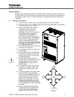
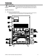
4.1.4
Control Circuit and External Battery Interface Connections
The following illustrates the wiring connections of the Control Circuits and Battery Interface
Circuits.
NOTE: Control circuit wiring should be routed in it’s own conduit. Do not route control circuit
wiring through conduit containing UPS power cables.
TB2
TB3
CUSTOMER CONNECTIONS
TB2 Connections
1 – Low Battery
2 – Battery Discharge
3 – Fault
4 – Not Used
5 – Inverter Supply
6 – Inverter Supply
7 – Remote Run (P24A3)
8 – Remote Run
9 – Remote Stop (P24A3)
10 – Remote Stop
11 – Bypass
12 Common
13 - EPO
14 - EPO
TB3 Connections
3 – Battery Shunt Trip Out
4 – Battery Shunt Trip Out
5 – Battery AUX In
6 – Battery AUX In
4.1.5
Recommended Wire Size and Tightening Torque UPS Control and Battery Interface
Minimum Wire Size and Tightening Torque for UPS Control and Battery Interface Circuits
USE MINIMUM 75° C COPPER WIRING
TERMINAL (TERMINAL #)
AWG
TIGHTENING TORQUE
*UPS CONTROL CIRCUITS (1-18)
14-16
8 in-lbs.
*BATTERY CONTROL CIRCUITS (3-6)
14-16
8 in-lbs.
*Indicates Class 1 wiring method is to be used.
Содержание 4200FA XT
Страница 2: ...4200FA XT 80kVA Installation and Operation Manual ...
Страница 4: ...4200FA XT 80kVA Installation and Operation Manual ...
Страница 67: ......


