background image

Micro-Master Touch User Guide

47

© 2014 Toro Australia Pty Ltd

Ver 1.2, June 2014

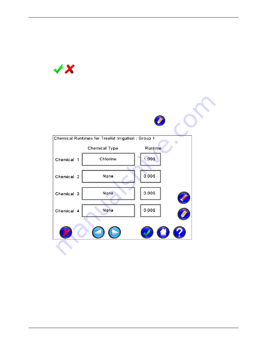
display the Group Edit screen.

Group Chemical Runtimes

The runtimes for each chemical group in the program.  Selecting the button and clicking Edit will
display the Chemical Edit screen.


Program Enabled

Programs can be enabled or disabled.  The icon shows the current enabled state of the Program. 
Clicking on the tick (cross) will change the Program to disabled (enabled).

9.2.4

Chemical Edit

The Chemical Edit screen is displayed by pressing the 

 icon on the Program Edit - Sequential

or Program Edit - Grouping screen.

Figure 27 - Program Chemical Edit

In the example screen shown in Figure 27, only one chemical is used in this irrigation, and operates
for 1 minute in group 1.

Chemical Type

Each program can have up to four chemicals assigned.  Only the same four chemicals can be used
for all groups in the current program, but each program can have different chemicals.  Selecting the
chemical type button and clicking Edit will display the Chemical Selection screen.

Chemical Runtime

The runtime for this chemical for this program group.  Selecting the button and clicking Edit will

Содержание Micro-Master Series

Страница 1: ...2014 Toro Australia Pty Ltd Micro Master Touch User Guide Micro Master Series...

Страница 2: ......

Страница 3: ...of the Micro Master Touch features include Touch Screen Control Modular Construction for ease of expansion and repair Life Support Powerful Rules capability Multiple Pump Sets Multiple Filter Banks In...

Страница 4: ...ams and source code that may accompany it In no event shall the publisher and the author be liable for any loss of profit or any other commercial damage caused or alleged to have been caused directly...

Страница 5: ...11 4 7 12 Volt DC Operation 5 Controller Setup and Configuration 13 13 5 1 Overview 15 5 2 Setup Selection 17 5 3 System Setup and Upgrade 18 5 4 Unit Configuration 19 5 5 Expansion Module Configurat...

Страница 6: ...Set Edit 68 11 4 Pump Set Advanced Parameters 12 Filter Banks 71 71 12 1 Overview and Operation 73 12 2 Filter Bank List 74 12 3 Filter Bank Edit 75 12 4 Filter Bank Advanced Parameters 13 Chemicals 7...

Страница 7: ...gue Edit 14 8 3 110 Analogue Status and Totals 14 8 4 110 14 9 Switch Sensors 110 Overview and Operation 14 9 1 112 Switch Sensor List 14 9 2 113 Switch Sensor Edit 14 9 3 114 Switch Input Status and...

Страница 8: ...ical Specifications 132 21 Fault Finding 135 135 21 1 Overview 136 21 2 Fault Finding Flow Chart 136 21 3 Fault Finding Possible Cause 137 21 4 Diagnostics 138 21 5 Checking Field Wiring and Valve Cur...

Страница 9: ...rnet interface cards Each Micro Master Touch controller can be expanded out to 160 stations using additional Remote controller units up to 4 units Communication between units is achieved by RS485 comm...

Страница 10: ...A burst pipe in a pump shed for example can do a lot of damage Do ensure that all wiring holes in the case are sealed Ants mice and slugs can also destroy the unit if they are allowed entry and will...

Страница 11: ...ions 1 and 2 and a flushing valve station 4 is connected to both zones to drain solids from the line after irrigation The treelot irrigation program operates in grouping mode The storage tank is circu...

Страница 12: ...8 16 24 32 station variants MMTOUCH STN Micro Master Touch 8 Station Relay Module MMTOUCH DIG Micro Master Touch 8 Input Digital Input Module MMTOUCH ANL Micro Master Touch 8 Input Analogue Input Mod...

Страница 13: ...o Master Touch User Guide 5 2014 Toro Australia Pty Ltd Ver 1 2 June 2014 The diagram below shows the breakdown of a Micro Master Touch Master Unit Figure 2 Micro Master Touch Master Unit Exploded Dia...

Страница 14: ...o Master Touch User Guide 6 2014 Toro Australia Pty Ltd Ver 1 2 June 2014 The diagram below shows the breakdown of a Micro Master Touch Remote Unit Figure 3 Micro Master Touch Remote Unit Exploded Dia...

Страница 15: ...sed to slip into the keyhole slot To secure and stabilise the controller drive additional screws through the bottom mounting holes NOTE When mounting the controller to a sheet metal wall it is essenti...

Страница 16: ...xpansion modules 5 6 are fitted on edge Ensure that all the gold pins enter the header connector on the module and the screw mount aligns with the bracket then insert the screw Typically this is where...

Страница 17: ...ouch Remote Units each fitted with a variety of expansion modules Configuration of a Touch Unit as either a Master Unit or Remote Unit is performed via a four switch block numbered 1 to 4 on the mothe...

Страница 18: ...ottom cover 2 Route 1 wire from each valve though one of the three holes in the bottom of the controller case Insert each lead into the appropriate terminal on the connector For ease of wiring the con...

Страница 19: ...ars at 40 degrees Celsius In the long term an alkaline battery will be more reliable and cheaper than an equivalent NiCad battery They are replaced every 1 to 2 years depending on the number of power...

Страница 20: ...2 June 2014 1 Remove the 4 way connector from the motherboard 2 Plug in the 12VDC adaptor plug supplied with the controller 3 Connect the RED lead to 12VDC 4 Connect the BLACK lead 0VDC 5 Connect Ear...

Страница 21: ...ll request confirmation If approved the controller will reboot and attempt to update the firmware from the file on the USB device If a compatible file is not found the controller will abort the firmwa...

Страница 22: ...mote Unit Unit 1 then Field Modules should be added as Unit 2 Module 1 etc Access PIN Numbers The controller supports two options for restricting access to levels of functionality in the controller On...

Страница 23: ...lays the System Setup screen to allow edit and control of the Controller ID System Date and Time and allow in field upgrade of the controller firmware Global Setup and Configuration Pressing this icon...

Страница 24: ...ble controller communication module options Life Support Setup and Configuration Pressing this icon displays the Life Support Setup screen to allow edit and control of the Life Support features of the...

Страница 25: ...changing the background to light blue Selecting the Date Time then clicking Edit will display the Time Edit screen allowing the controller date and time to be changed Version This item displays the c...

Страница 26: ...number 2 The status for the unit is updated every 20 seconds and the current runtime status is shown The status shown is dependant on the type of modules in the remote unit For analogue sensors the cu...

Страница 27: ...dered an absolute minimum without severely impacting station operations Unit Module Status This area displays the current status of the unit expansion modules Unit Communication Method Clicking on the...

Страница 28: ...on Module will select the item changing the background to light blue It will also show the build date serial number and communication method for the selected expansion module Scan Expansion Modules Th...

Страница 29: ...ll the antenna prior to mounting the Solar Panel assembly onto the mast Remember the higher the antenna the better the coverage Loosen the nut on the base of the antenna and slide the antenna into the...

Страница 30: ...the top and bottom of the Module Mounting Plate Using the 3 16 bolts and nuts attach the RMT Field Module to the Module Mounting Plate and tighten Remove the front cover of the Radio Master for Touch...

Страница 31: ...ires Strip 5mm of insulation from the solenoid wires Connect the solenoid latch wire to the Connector Block positions marked L for the appropriate valve number For a Bermad S985 solenoid the Latch Wir...

Страница 32: ...e Touch controllers allows use on up to 8 separate channels By default the radio channel is set to channel 1 If multiple Touch systems have been installed in the surrounding area it may be necessary t...

Страница 33: ...PosiSense and PosiSense solenoids in any mix across the valve positions Setting PosiSense is achieved in a similar manner as described above The ON LED will flash 3 times on a successful command For e...

Страница 34: ...n OFF manually To turn a valve ON OFF press the relevant button numbered 1 to 8 on the keyboard When the key is pressed the ON LED will flash to show the valve is turning on or the OFF LED will flash...

Страница 35: ...ecting the button and then clicking Edit will display an appropriate screen to allow modification of available communication parameters for the selected communication module Communication Module Statu...

Страница 36: ...Full Access item will select the item changing the background of the item to light blue Selecting the button and then clicking Edit will display the Number Edit screen PIN Timeout Clicking on the PIN...

Страница 37: ...e 2014 Micro Master Touch Controller Output Commissioning Sheet Unit No Station Number Valve Location Valve Current Wire Colour Radio Address Comments 1 2 3 4 5 6 7 8 9 10 11 12 13 14 15 16 17 18 19 2...

Страница 38: ...mation screen If confirmed the controller will reset the controller totals and logs to zero This option does not erase the configuration of programs sensors etc Backup Controller Clicking on Backup Co...

Страница 39: ...are able to start A cross indicates that all controller programs will not start Clicking the tick cross will disable enable the programs Rain Switch A tick indicates that the controller is in a rain...

Страница 40: ...n the navigation area allow the user to accept or cancel any changes to the function parameters or navigate to the next entry in the function A home button returns the user directly to the main menu w...

Страница 41: ...guration If the screen timeout occurs before the accept button is pressed all current modifications will be lost The cancel button cancels all changes including changes in the advanced edit screens an...

Страница 42: ...graphically in the following diagram using the Pump Set subsystem as an example Home Screen Pump Set List Previous Pump Set Pump Set Edit Next Pump Set Previous Advanced Pump Parameters pages for the...

Страница 43: ...ve power and extend the LCD lifespan If the screen is blanked pressing anywhere on the screen for 2 seconds and releasing will reactivate the screen and display this Home Screen Each major function of...

Страница 44: ...ssing this icon displays the sensors list to edit and control sensors Manual Pressing this icon displays the manual control screen Reports Pressing this icon displays the reports screen Setup Pressing...

Страница 45: ...he status screen also displays active inputs outputs filters and chemicals A number of lines are provided in each section The lines will scroll if there are more lines to be displayed For example if t...

Страница 46: ...program determines the next valid group and moves to the Change Group state The program attempts to maintain a consistent number of active stations while changing groups If there are no delays statio...

Страница 47: ...down runtime Change Group Holding turn off valves in current group Unholding turn on valves incurrent group Stopping turn off valves stop pump set stop filter set Group Runtime expired Irrigation com...

Страница 48: ...hange the parameter for all programs that have Use Program 1 Config enabled When Use Program 1 Config is disabled for a particular program the shared parameters are copied from Program 1 to the partic...

Страница 49: ...ed is zero the program will run once Program Delays The Micro Master Touch controller has 4 different delays PreStart Delay If set a PreStart Delay begins at the set start time or when start is presse...

Страница 50: ...Rules are considered valid when all of the input conditions for the rule are met Start Sensor The Start Sensor will start irrigation when valid Stop Sensor The Stop Sensor stops the current irrigatio...

Страница 51: ...but does not have start times hence can only be run manually All other programs shown are empty Program Names and Status Each line in this list displays the name of the Program if assigned and the cu...

Страница 52: ...the program is currently held pressing this icon will resume program operation Program Skip Pressing this icon in the action area will skip the selected program from the current group to the next gro...

Страница 53: ...The Day Table Start Times and Cycle Counts for this Program Selecting the button and clicking Edit will display the Day Table Edit screen Station Runtime The runtimes for each station in the program S...

Страница 54: ...in adding a 1 minute line flushing cycle Program Name Each Program can be assigned a name Names are limited to 20 characters Selecting the name button and clicking Edit will display the Text Edit scre...

Страница 55: ...ical Edit screen is displayed by pressing the icon on the Program Edit Sequential or Program Edit Grouping screen Figure 27 Program Chemical Edit In the example screen shown in Figure 27 only one chem...

Страница 56: ...rigation actions available are None Irrig and Irr Ch Irrig is irrigation only Irr Ch is irrigation with chemical injection Cycles Clicking on a Cycles button displays the Number Edit screen allowing m...

Страница 57: ...arameters shared with Program 1 are indicated by the next to the parameter For flexibility individual programs can use their own configuration Use Program 1 Config When ticked this program will share...

Страница 58: ...clicking Edit will display the Program List screen 9 2 7 Program Delays The Program Delays screen is the second page of Advanced Program Parameters and is displayed by pressing the icon on the Program...

Страница 59: ...or Program Edit Grouping screen and selecting the page by pressing the icon twice Figure 31 Program Advanced Parameters Edit Page 3 In the example screen shown in Figure 31 the Treelot irrigation wil...

Страница 60: ...Clicking on the Pump Set item will select the item changing the background of the item to light blue Selecting the button and then clicking Edit will display the Control Select screen Program Filter S...

Страница 61: ...icon on the Program Edit Sequential or Program Edit Grouping screen and selecting the next page by pressing the icon four times Figure 33 Program Advanced Parameters Edit Page 5 Program Status This se...

Страница 62: ...letes the Station is started for the specified runtime If the irrigation units are volumetric the volume units are the same as the allocated Flow Meter When active the Station program can be held by a...

Страница 63: ...ation program completes it is possible to automatically start another Station or Irrigation Program This allows staggered program starts PreStart Delay A PreStart Delay starts the allocated Pump Set b...

Страница 64: ...ated Flow Meter can be either a Flow Meter or an Aggregate Flow Meter If a Flow Meter is allocated the flow will be logged Ignore Rain Switch This option sets the Station to ignore the Global Rain Swi...

Страница 65: ...erent icons Indicates a Station is empty or is disabled An empty Station displays Empty a disabled Station displays the name of the Station Indicates a Station is idle A Station is idle when the input...

Страница 66: ...lay the Text Edit screen Station Water budget The Water Budget for this Station Selecting the button and clicking Edit will display the Number Edit screen Station Day Table The Day Table Start Times a...

Страница 67: ...t screen Figure 37 Station Advanced Parameters Page 1 Use Station 1 Config This option sets the Station to use the same configuration units as Station 1 When enabled changing the parameters in this St...

Страница 68: ...essing the icon Figure 38 Station Advanced Parameters Page 2 PreStart Delay Clicking on PreStart Delay will select the item changing the background of the item to light blue Selecting the button and t...

Страница 69: ...Start Sensor will select the item changing the background of the item to light blue Selecting the button and then clicking Edit will display the Control Selection screen Stop Sensor Clicking on Stop S...

Страница 70: ...the Control Selection screen Filter Set Clicking on Filter Set will select the item changing the background of the item to light blue Selecting the button and then clicking Edit will display the Contr...

Страница 71: ...g the page by pressing the icon four times Figure 41 Station Advanced Parameters Page 5 Station Status This section shows the current status of the station and remaining run or delay time depending on...

Страница 72: ...inter pump delay setting If a flow meter is allocated further pumps will be started or stopped as required based on the flow rate from the flow meter If the VFD pump setting is ticked pump 1 will alw...

Страница 73: ...starts may reduce the electrical power required at pump start and prevent hydraulic shock to the system water pipes Pump Off Delay The Pump Off Delay can be used to keep pumps running for a set period...

Страница 74: ...ssing the icon on the Home Screen Figure 43 Pump Set List Pump Set Names and Status Each line in this list displays the name of the Pump Set if assigned and the current status of the Pump Set Clicking...

Страница 75: ...me Names are limited to 20 characters Selecting the name button and clicking Edit will display the Text Edit screen Pump Station Output Clicking on a pump station will select the station changing the...

Страница 76: ...pump delays Page 2 allocates a flow meter for the pump The flow meter does not have to be different for each pump set The same flow meter can be used for any or all programs chemicals and pump sets P...

Страница 77: ...screen is the second page of Advanced Pump Set Parameters and is displayed by pressing the icon on the Pump Set Edit screen and pressing the icon Figure 46 Pump Set Advanced Parameters Edit Page 2 All...

Страница 78: ...ump Set Edit screen and selecting the page by pressing the icon twice Figure 47 Pump Set Advanced Parameters Edit Page 3 Pump Set Status This section shows the current status of the pump and remaining...

Страница 79: ...the system to stabilise before filter washing may be initiated Following the Initial PD Delay the filter bank enters a PD Backup Delay During this delay a switch closure on the PD Input will start a f...

Страница 80: ...ycle Delay Minimum Time between Filter Flushing Cycles This is the delay time between filter back flush cycles It acts in conjunction with the PD switch and effectively delays a Pressure Differential...

Страница 81: ...on on the Home Screen Figure 50 Filter Bank List Filter Bank Names and Status Each line in this list displays the name of the Filter Bank if assigned and the current status of the Filter Bank Clicking...

Страница 82: ...Filter Bank is active when the Filter Bank is closed 12 3 Filter Bank Edit The Filter Bank Edit screen is displayed by pressing the icon on the Filter Bank List screen Figure 51 Filter Bank Edit In th...

Страница 83: ...lter Bank Advanced Parameters Filter Parameters The Filter Parameters screen is the first page of Advanced Filter Bank Parameters and is displayed by pressing the icon on the Filter Bank Edit screen F...

Страница 84: ...n This option allows chemical injection to be paused during a filtration event Clicking on the tick cross will change the Filter Bank to disabled enabled Filter Bank Status and Totals The Status and T...

Страница 85: ...al into the soil The Pre wet Mixing time is always in minutes and seconds Chemical Injection Operation When chemical injection is required by an irrigation program the chemical injection begins the pr...

Страница 86: ...If volumetric the units are the same as the allocated flow meter Prewet Mixing Station The allocated station can be any station in the controller or an output on the main screen panel Prewet Mixing R...

Страница 87: ...the Chemical changing the background of the selected Chemical to light blue Selecting a Chemical and then clicking Edit will display the Chemical Edit screen Chemical Status Icons The status of each C...

Страница 88: ...acters Selecting the name button and clicking Edit will display the Text Edit screen Chemical Enabled Chemicals can be enabled or disabled Clicking on the tick cross will change the Chemical to disabl...

Страница 89: ...rewet station will stop when injection commences 13 4 Chemical Advanced Parameters The Status and Totals screen is the only page of Advanced Chemical Parameters and is displayed by pressing the icon o...

Страница 90: ...and can be used as general purpose inputs for use as a parameter in rules or as a pulse flow meter Analogue Sensors can be located in one of the Expansion Module positions and can be used as general p...

Страница 91: ...nsor Rules Pressing this icon displays the Sensor Rule list to edit and control Sensor Rules Flow Meters Pressing this icon displays the Flow Meter list to edit and control Flow Meters Aggregate Flow...

Страница 92: ...ut can be sourced from various sources It could be the active status of a program station filter chemical or pump It could be the state of any control sensor in the control sensor system including the...

Страница 93: ...m 2 runs a transfer program to move water from the dam to the tank When the tank is empty we want to hold Program 1 while the tank transfer program runs Therefore a rule that would encompass this scen...

Страница 94: ...ed and the current status of the rule Clicking on a name will select the Rule changing the background of the selected Rule to light blue Selecting a Rule and then clicking Edit will display the Rule E...

Страница 95: ...culation program Rule Name Each rule can be assigned a name Names are limited to 20 characters Selecting the name button and clicking Edit will display the Text Edit screen Rule Enabled Rules can be e...

Страница 96: ...n the Rule Edit screen Figure 62 Rule Status and Totals Rule Status This section shows the current status of the rule Rule Totals This section shows the current totals for the rule Clicking the clear...

Страница 97: ...limits and time to calculate the current flow rate produces a flow rate measurement that is responsive to large changes in flow without excessive fluctuations in the displayed flow during flows of rel...

Страница 98: ...Flow Meter Any switch input on the main screen panel or digital input module in an Expansion Module position can be selected as the input for the flow meter Update Rate This setting only affects flow...

Страница 99: ...ect the Flow Meter changing the background of the selected Flow Meter to light blue Selecting a Flow Meter and then clicking Edit will display the Flow Meter Edit screen Flow Meter Status Icons The st...

Страница 100: ...he current flow If the flow increases above 1700 litres per minute the flow meter becomes triggered and could be used as a trigger to stop irrigation Flow Meter Name Each Flow Meter can be assigned a...

Страница 101: ...then clicking Edit will display the Control Selection screen Flow Meter Total Flow This button shows the real time total flow for the Flow Meter Selecting the total button and clicking Edit or Clear w...

Страница 102: ...For example an oval could be supplied from an on site dam when water is available and from main town supply when the dam is empty using Rules to determine which supply is used Using an aggregate flow...

Страница 103: ...ggregate Flow Meter Operation Schematic Aggregate Flow Meter Parameters Flow Meter 1 4 This setting shows the four flow meters used in an aggregate flow meter If no flow meter is required the setting...

Страница 104: ...en clicking Edit will display the Aggregate Edit screen Aggregate Flow Meter Status Icons The status of each Aggregate is shown graphically using different icons Indicates an Aggregate Flow Meter is e...

Страница 105: ...second flow meter measures only the boundary flow The total flow would then show only the flow from the Treelot irrigation Aggregate flow units are always kilolitres Aggregate Flow Meter Name Each Agg...

Страница 106: ...o zero Aggregate Flow Meter Enabled Aggregate Flow Meters can be enabled or disabled Clicking on the tick cross will change the Aggregate Flow Meter to disabled enabled 14 5 4 Aggregate Status and Tot...

Страница 107: ...nsor can be named and can be enabled or disabled Digital Sensor Operation When a digital sensor is enabled the digital input is monitored every second If the digital sensor detects the input is closed...

Страница 108: ...cking on a name will select the Digital changing the background of the selected Digital to light blue Selecting a Digital and then clicking Edit will display the Digital Edit screen Digital Status Ico...

Страница 109: ...to 20 characters Selecting the name button and clicking Edit will display the Text Edit screen Digital Sensor Enabled Digital Inputs can be enabled or disabled Clicking on the tick cross will change t...

Страница 110: ...view The Micro Master Touch supports one rain bucket sensor The Rain Bucket can be setup to cancel irrigation if the accumulative rainfall in a defined period between 1 to 7 days exceeds a predefined...

Страница 111: ...ed over the number of days specified in the Rain Days setting If the total rain exceeds the Rain Cancel setting the rain bucket disables all irrigation except those programs with the Ignore Rainswitch...

Страница 112: ...or the rain bucket The rain rate and total rainfall are updated for every pulse sensed on the allocated input The total rain is logged each hour for rain day calculation Note that the total rainfall a...

Страница 113: ...the sensor to disabled enabled 14 8 Analogue Sensors 14 8 1 Overview and Operation The Micro Master Touch supports up to 160 independent analogue sensors An analogue sensor can be used as a flow meter...

Страница 114: ...le measurement for the flow meter This value is the reading that will be displayed by the controller when the 4 20mA sensor is measuring 20mA current The calibration figure will be found in the specif...

Страница 115: ...to light blue Selecting a Analogue and then clicking Edit will display the Analogue Edit screen Analogue Sensor Status Icons The status of each Analogue Sensor is shown graphically using different ic...

Страница 116: ...measured humidity At 20mA current the humidity is 100 and the sensor is triggered at 85 The units shown for the sensor are not used in any calculations They are used in reports and may be any text An...

Страница 117: ...value is the reading that will be displayed by the controller when the 4 20mA sensor is measuring 20mA current Selecting the 20mA calibration button and clicking Edit will display the Number Edit scr...

Страница 118: ...ndependent switch sensor inputs Switch sensor inputs are located on the front panel and can be used as general purpose switch input sensors or inputs for flow meters Each Switch Sensor can be named an...

Страница 119: ...rrigation program requires time to fill mainlines at the start of irrigation a longer time may be required than during a shift change when the mainlines are already filled Switch Sensor Operation When...

Страница 120: ...atus of the Input Clicking on a name will select the Input changing the background of the selected Input to light blue Selecting a Input and then clicking Edit will display the Input Edit screen Switc...

Страница 121: ...he name button and clicking Edit will display the Text Edit screen Initial Delay The setting adjusts the delay time used during initial irrigation start Selecting the Initial Delay button and clicking...

Страница 122: ...e of Advanced Switch Sensor Parameters and is displayed by pressing the icon on the Switch Sensor Edit screen Figure 84 Switch Sensor Status and Totals Switch Sensor Status This section shows the curr...

Страница 123: ...al Operation Spot Water Manual Spot Water Operation begins by selecting the required stations allocating a Pump Set if required and setting a runtime and units Spot Water irrigation commences when the...

Страница 124: ...eration to that mode Manual Runtime and Units The Manual Operation runtime can be set to hours minutes or minutes seconds Selecting the runtime button and clicking Edit will display the Number Edit sc...

Страница 125: ...tion If manual operation is running this icon will stop the operation Manual Operation Hold Unhold When not held this icon will hold the spot watering or station walk through operation If manual opera...

Страница 126: ...can hold 1000 reports in the global configuration and fault reports and can hold 20 000 reports in the irrigation reports Individual Report groups can be enabled or disabled in the Report Settings pa...

Страница 127: ...Reports list to allow edit and control of Fault Reports 16 3 Report List The list screens for each of the Report groups is displayed by pressing the icon for the report group on the Report Selection S...

Страница 128: ...report and log category USB Export If a valid flash disk USB Thumb Drive is connected to the USB connector on the front panel this icon will export all reports and logs from the current category to a...

Страница 129: ...re are nine advanced setting pages for the report system Each page groups a related set of report entries that may be enabled The Report Settings pages are displayed by pressing the icon on the Report...

Страница 130: ...Micro Master Touch User Guide 122 2014 Toro Australia Pty Ltd Ver 1 2 June 2014 Figure 91 Report Setting Pages...

Страница 131: ...rammed irrigation program in Sequential mode on that module only In Life Support Level 2 Sequential mode each station on the unit 8 stations can run an independently adjustable runtime Each stations r...

Страница 132: ...upport would need to be setup for each unit Life Support Master Remote Clicking on the Master Remote item will select the item changing the background of the selected item to light blue Selecting the...

Страница 133: ...changing the background of the selected item to light blue Selecting a runtime and then clicking Edit will display the Time Edit screen Life Support Group Stations Clicking on a Group item will select...

Страница 134: ...ssible common edit screens that could be displayed These screens include text number time and others This section describes these generic edit screens 18 1 Text Edit Figure 93 Text Edit Screen This sc...

Страница 135: ...r to 61 A blank number if 0 is deleted will be accepted as a zero number 18 3 Time Edit Figure 95 Time and Duration Edit Screen This screen allows the modification of a runtime or time entry The Delet...

Страница 136: ...the front panel Clicking on Prev Next will move the display to the previous next group in the current program Clicking on a button will turn the station on or off for the group The total shown at the...

Страница 137: ...lection If the current control sensor has more than 8 items a range of page select buttons will be shown Clicking a page selection button will display the eight control sensor listed under the button...

Страница 138: ...le on the time axis either the date or time will be displayed at six points on the axis Note that the time axis may not be continuous In the example above if the Treelot Flow Meter is disabled for a p...

Страница 139: ...iver mount enables the TMR 1 system to be quickly installed and ready for operation then easily moved from site to site as needed The TMR 1 system is designed for simple plug and play operation A TMR...

Страница 140: ...e one pump Output Power Station Capacity 24 volt AC at 2 0 Amp max 8 2 watt valves 12 volt DC at 2 0 Amp max Pump Start Capacity 24 volt AC at 1 0 Amp max 12 volt DC at 1 0 Amp max Total Unit Capacity...

Страница 141: ...um 95 non condensing Hardware Processors High Performance Low Power AVR 32 UC 32 Bit Microcontroller High performance Low power AVR 8 bit Microcontrollers Processor protection Varistor 1000 amp 20 use...

Страница 142: ...n rear of front panel Output Board Rear Mounted to base of cabinet with common connector TMR socket and 24Vac Hotpoint Logic and output boards interconnect by 14 way flat ribbon polarised connector Sa...

Страница 143: ...LED If the LED on an Expansion Module is not flashing or it is flashing at odd intervals then that Expansion Unit is faulty If no Expansion Modules are flashing their LEDs simultaneously then it is po...

Страница 144: ...Controller Fault Replace Module or Return for service Isolate Faulty Module Rectify Field Wiring No Yes Fail No Yes No OK Yes Fail OK Yes Fail OK Yes Fail No Fail Controller Fault Return for service F...

Страница 145: ...on Switch off the controller and remove the standby battery Wait 5 seconds and switch on again Table 2 Fault Finding Possible Causes 21 4 Diagnostics The Touch Controller uses various memory technolo...

Страница 146: ...he test will timeout and continue to completion Clear Diagnostics Selecting the Clear icon requests confirmation to clear all diagnostic results to Fail or 0 Help Pressing this icon displays a help sc...

Страница 147: ...ken during the initial commissioning Use the Manual Walk Through Spot Water option to turn stations on in sequence and check the station voltage at the terminal The station voltage must be over 24VAC...

Страница 148: ...s is approx 16VAC This is due to the feedback through the surge protection devices The surge protection devices have a very high impedance to normal voltages Therefore no current can be sourced from t...

Страница 149: ...d provided that the following conditions are met 1 Redistributions of source code must retain the above copyright notice this list of conditions and the following disclaimer 2 Redistributions in binar...

Страница 150: ...gation will be Paused or Suspended until the contacts open gain HOME SCREEN Controller display in normal time of day outside of irrigation cycle or manual operation MANUAL Allows a single station to b...

Страница 151: ...2 June 2014 START TIME The time of day when irrigation will start STATION A controller output or terminal to connect a valve to VALVE OUTPUT Same as station WATER BUDGET A percentage value that will g...

Страница 152: ...Toro Australia Pty Ltd 53 Howards Road Beverley SA 5009 A B N 47 001 310 443 Customer Service Phone 1300 130 898 Fax 08 8234 2940...

Отзывы: