


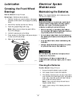


g343369
Figure 31
1.
Blade (side previously measured)
2.
Measurement (position used previously)
3.
Opposing side of blade being moved into measurement
position
5.
Measure from the tip of the blade to the flat
surface (
).
Note:
The variance should be no more than
3 mm (1/8 inch).
g343365
Figure 32
1.
Opposite blade edge (in position for measuring)
2.
Level surface
3.
Second measured distance between blade and surface (B)
A.
If the difference between A and B is greater
than 3 mm (1/8 inch), replace the blade with
a new blade; refer to
(page 29)
and
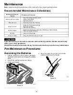
Installing the Blades (page
.
Note:
If a bent blade is replaced with a
new blade, and the dimension obtained
continues to exceed 3 mm (1/8 inch), the
blade spindle could be bent. Contact an
Authorized Service Dealer for service.
B.
If the variance is within constraints, move to
the next blade.
6.
Repeat this procedure on each blade.
Removing the Blades
Replace the blades if they hit a solid object, or if the
blade is out of balance or bent.
1.
Place a woodblock between the blade and
mower housing to prevent the blade from
turning.
2.
Hold the blade end using a rag or thickly padded
glove.
3.
Remove the blade.
g343371
Figure 33
1.
Spindle shaft
4.
Curved washer
2.
Adapter
5.
Nut
3.
Blade
Sharpening the Blades
1.
Use a file to sharpen the cutting edge at both
ends of the blade (
Note:
Maintain the original angle.
Note:
The blade retains its balance if the same
amount of material is removed from both cutting
edges.
g000552
Figure 34
1.
Sharpen at original angle.
2.
Check the balance of the blade by putting it on a
blade balancer (
).
Note:
If the blade stays in a horizontal position,
the blade is balanced and can be used.
29
Содержание 75500
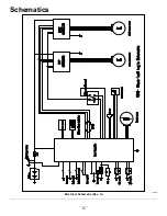
Страница 33: ...Schematics g355680 Electrical Schematic Rev A 33 ...
Страница 34: ...Notes ...
Страница 35: ...Notes ...