


5.
Insert the wire harness connectors into the
control panel hole.
6.
Remove the 4 screws securing the cover to the
left side of the machine. Repeat for the right
side.
g358653
Figure 20
1.
Hex-head screw (4 each side)
7.
Remove the 3 rear screws from the cover.
g358652
Figure 21
8.
Remove the 4 top screws from the cover.
g358654
Figure 22
9.
Carefully lift the cover and set it down next to
the machine.
Note:
You do not need to disconnect the wire
harness from the controls.
g358651
Figure 23
10.
Reverse the procedure to install the cover.
Important:
After maintenance, ensure that there
are no open circuits or loose wiring.
24
Содержание 75500
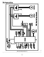
Страница 33: ...Schematics g355680 Electrical Schematic Rev A 33 ...
Страница 34: ...Notes ...
Страница 35: ...Notes ...