


SS-OCT System Base Unit
Chapter 4: System Operation
Page 28
MTN013142-D02
Use the jog buttons or the input field in the reference stage control to move the reference stage in both
directions so that you can see how the image position is shifted.
Find a value for the reference stage control so that the image is not “flipped” (upside-down). Use a
sample where you know for sure what the top surface looks like.
Hit the auto-adjust button (see software Manual) to adjust the dynamic range of your B-scan.
When using the IR card for adjustment, your B-scan image should look as shown in Figure 34.
Figure 34
B-Scan of an IR Viewing Card
After basic alignment, you need to adjust the focus position inside your sample by use of the fine focus adjuster
(see Figure 25) of the OCT-Stand. Then, the final position of the OCT image in the B-scan or volume scan can
be set using the reference stage control again. Vary the value to move the image up and down until you achieve
the desired location. Next time the system is restarted, the reference length will be set according to the last
modifications made.
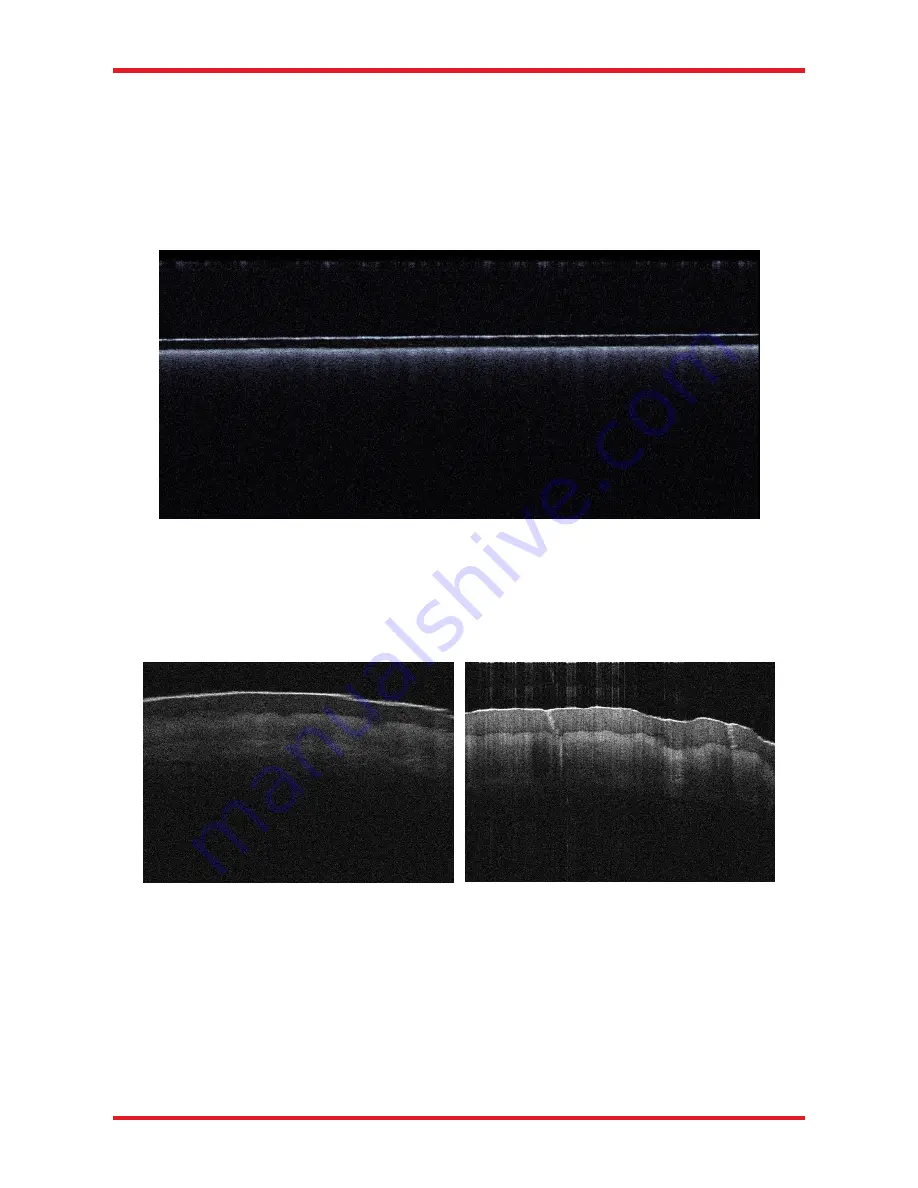
Figure 35
B-Scan of a Fingertip Out of Focus and In Focus
In Figure 35, two images of a fingertip are shown, the left is out of focus and the right is in focus.
The focus can usually be identified by one or more of the following features:
Sharp (thin) features in lateral direction.
Higher contrast (i.e. a strong signal). Note, that the focus does not always have to be on the top surface
of your sample, but needs to be adjusted to the layer of interest in your sample.
If the sample that you are using to find the focus is highly reflective, you are likely to get saturation
resulting in strong horizontal lines in the image.


