


Connectors inside
the sample compartment
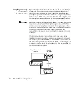
The following illustration shows the locations of the electrical
connectors inside the sample compartment:
Detector/Motors
Auxiliary
Purge
Out
Optional pass-through connector
for communication or other signal
Accessory connector for detector
signal or accessory control and power
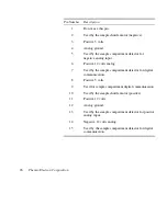
Detector/Motors
– If you have a photoacoustic or other accessory
that has a detector or motor located in the spectrometer sample
compartment, connect the cable from the detector or motor to this
standard connector. This is
not
a pass-through connector. See
“Detector/Motors connector” for information about using this
connector to connect custom hardware.
Auxiliary
– Six pins on this optional connector can be used for
passing DC power input or other signals from the Auxiliary 1 and
Auxiliary 2 connectors on the front panel to an accessory. For
example, the automatic sample wheel and the ProfilIR accessory get
DC power through this connector when the DC power output of an
AC-to-DC converter is attached to the Auxiliary 1 connector on the
front panel. See “Using connectors for custom accessories” for
information about which pins are available for use.
92 Thermo Electron Corporation