KRB-5404
15
The following procedure makes it easy to make connections with plug-in tab terminals (#187) of position switches, control
circuit terminals, and auxiliary switches.
(1) Draw out the breaker body to the removed position, and remove it using an optional lifter or lifting plate. Refer to sections 4-2-2
and 2-1-2.
(2) If the ACB is equipped with the control terminal block cover, loosen both the cover fixing screws and remove the cover.
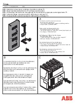
(3) Remove the terminal block fixing screws shown in Fig. 11.
Fig. 11 Terminal block fixing screws
(4) Tilt the terminal block down as shown in Fig. 12. After connecting wires, tilt the terminal block up again and fix it with the
terminal block fixing screws.
Fig. 12 Terminal block tilted down
Connect the control wire to a com. terminal as shown in Fig. 13.
Fig. 13 Com terminal connection
If any work is done near the ACB that have been installed, protect the openings of the ACB with appropriate covers to prevent
spatters, metal chips, wire cuttings or other foreign objects from entering the ACB.
Terminal block fixing screws
Hex head M6 × 10 (4) (red),
with spring washer and flat
washer
Tightening torque: 4.7 - 5.9 N·m
Auxiliary switches
Cover fixing screw
Auxiliary switch terminal screw
(Control terminal screw)
(Position switch terminal screw)
Pan head M4 × 8,
with spring washer and terminal
washer
Tightening torque: 1.3 - 1.7 N·m
Com. terminals
Control wire
Cross sectional area of the control
wire: 1.5 mm
2
(AWG16)
Small flat-blade screwdriver
* If the gap above the com. terminal is
too small to insert the screwdriver,
unscrew the two communication
terminal block mounting screws (pan
head M4 × 8, red, with spring and flat
washers), remove the terminal block,
connect the control wire and reinstall
the terminal block.
The tightening
torque of the mounting screws is 1.3
– 1.7 N·m.
8 -9mm


