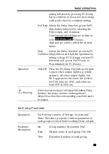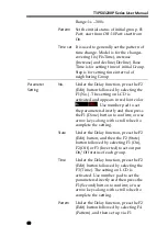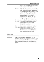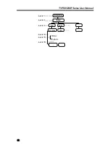
BASIC OPERATION
73
Schematic
diagram for
control signal
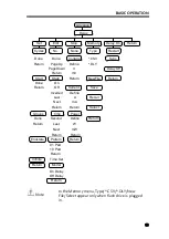
The control circuit of each port is illustrated as the
diagram below (D1 for example)
Key Function Description
Input/Output Mode
:
Key
Function
Operation Result
F1
Data Line
Select object to be set from D0 to D4
F2
Enable
Set to Enable or Disable function of the port
F3
Mode
Set which mode to adopt: Input Mode or Output
Mode
F4
Channel
Select corresponding channel: F1(CH1), F2 (CH2),
F3 (CH3), F4 (CH4)
F5
More
F6
Return
F5 (More) under Input Mode setting:
Key
Function
Operation Result
F1
Type
Select trigger type: F1(RiseEdge), F2 (FallEdge), F3
(Hi-Level), F4 (Lo-Level), , F5(States Input)
F2
Response
Set result after trigger response:
F1(Output) sets as ON, OFF or reverse Toggle
F2 (PWR.Mode) sets channel as power mode
F3 (Load Mode) set channel as load CV/CC/CR
mode
Содержание T3PS13206P
Страница 1: ... ...
Страница 106: ...T3PSX3200P Series User Manual 106 Register Commands OPC 187 OPC 187 ...
Страница 177: ...REMOTE CONTROL 177 Example SAV 1 Recalls the setting stored in memory 2 STATE02 ...
Страница 185: ...REMOTE CONTROL 185 Example STB Returns 81 if the status byte register is set to 0101 0001 ...
Страница 196: ...T3PSX3200P Series User Manual 196 Between chassis and DC power cord 30MΩ or above DC 500V ...
Страница 197: ... 0 0 0 1 2 3 4 5 6 7 8 8 9 3 3 3 45 6 990 0 0 9 0 0 0 9 0 0 0 0 9 7 7 88 8 1 931711 RevB ...

