RiverPro and RioPro ADCP Guide
October 2017
EAR-Controlled Technology Subject to Restrictions Contained on the Cover Page.
Page 143
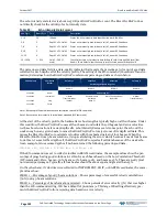
Table 19:
Fixed Leader Data Format
Hex Digit
Binary Byte
Field
Description
29-32
15,16
Blank after Transmit Contains the blanking distance used by the RiverPro/RioPro to allow the transmit cir-
cuits time to recover before the receive cycle begins. This value is fixed.
Scaling: LSD = 1 centimeter; Range = 0 to 9999 cm (328 feet)
33,34
17
Signal Processing
Mode
Contains the Signal Processing Mode. May be 0,1,2,3, or 31.
35,36
18
Low Corr Thresh
Contains the minimum threshold of correlation that water-profile data can have to
be considered good data. This is automatically varied by the RiverPro/RioPro
Scaling: LSD = 1 count; Range = 0 to 255 counts
37,38
19
cr# / No. code reps
Contains the number of code repetitions in the transmit pulse for non-surface layer
data. Uses Data Ping value.
Scaling: LSD = 1 count; Range = 0 to 255 counts
39,40
20
Percent Good
This field is always 1.
41-44
21,22
WE / Error Velocity
Threshold
This field, initially set by the WE-command, contains the actual threshold value used
to flag water-current data as good or bad. If the error velocity value exceeds this
threshold, the RiverPro/RioPro flags all four beams of the affected bin as bad.
Scaling: LSD = 1 mm/s; Range = 0 to 5000 mm/s
45,46
47,48
49,50
23
24
25
Minutes
Seconds
Hundredths
These fields, set by the TP-command, contain the amount of time between ping
groups in the ensemble. NOTE: The RiverPro/RioPro automatically extends the en-
semble interval (set by TE) if (WP x TP > TE).
51,52
26
EX / Coord Trans-
form
Contains the coordinate transformation processing parameters (EX-command).
These firmware switches indicate how the RiverPro/RioPro collected data.
xxx00xxx = NO TRANSFORMATION (BEAM COORDINATES)
xxx01xxx = INSTRUMENT COORDINATES
xxx10xxx = SHIP COORDINATES
xxx11xxx = EARTH COORDINATES
xxxxx1xx = TILTS (PITCH AND ROLL) USED IN SHIP
OR EARTH TRANSFORMATION
xxxxxx1x = 3-BEAM SOLUTION USED IF ONE BEAM IS
BELOW THE CORRELATION THRESHOLD SET
BY THE WC-COMMAND
xxxxxxx1 = BIN MAPPING USED
53-56
27,28
EA / Heading Align-
ment
Contains a correction factor for physical heading misalignment (EA-command).
Scaling: LSD = 0.01 degree; Range = -179.99 to 180.00 degrees
57-60
29,30
EB / Heading Bias
Contains a correction factor for electrical/magnetic heading bias (EB-command).
Scaling: LSD = 0.01 degree; Range = -179.99 to 180.00 degrees
61,62
31
EZ / Sensor Source
Contains the selected source of environmental sensor data (EZ-command). These
firmware switches indicate the following.
FIELD DESCRIPTION
x1xxxxxx = CALCULATES EC (SPEED OF SOUND) FROM
ED, ES, AND ET
xx1xxxxx = USES ED FROM DEPTH SENSOR
xxx3xxxx = USES EH FROM TRANSDUCER HEADING
SENSOR
Xxxx3xxx = USES EP FROM TRANSDUCER PITCH SENSOR
Xxxxx3xx = USES ER FROM TRANSDUCER ROLL SENSOR
xxxxxx1x = USES ES (SALINITY) FROM CONDUCTIVITY
SENSOR
xxxxxxx1 = USES ET FROM TRANSDUCER TEMPERATURE
SENSOR
NOTE: If the field = 0, or if the sensor is not available, the RiverPro/RioPro uses the
manual command setting. If the field = 3, the RiverPro/RioPro uses the reading from
the internal sensor or an external synchro sensor (only applicable to heading, roll,
and pitch). Although a “2” can be entered in the EZ-command string, the RiverPro/Ri-
oPro only displays a 0 (manual) or 1 or 3 (internal/external sensor).
63,64
32
Sensor Avail
This field reflects which sensors are available. The bit pattern is the same as listed for
the EZ-command (above).


