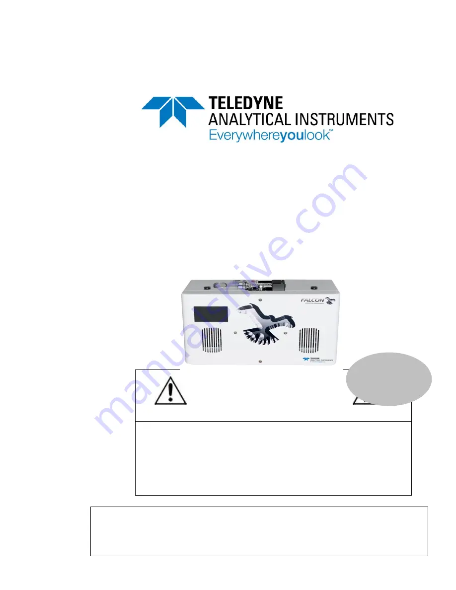
background image


Teledyne Analytical Instruments 


OPERATION AND MAINTENANCE 

MANUAL FOR 

FALCON GC


DANGER


Toxic and/or flammable gases or liquids may be present in this monitoring system. 

Personal protective equipment may be required when servicing this instrument. 

Hazardous voltages exist on certain components internally which may persist for 
a time even after the power is turned off and disconnected. 

Only authorized personnel should conduct maintenance and/or servicing. Before 
conducting any maintenance or servicing, consult with authorized 
supervisor/manager. 


P/N M 

DATE 07/30/19


Information included herein is controlled by the Export Administration Regulations 

(EAR) and requires an export license, license exception or other approval from the 
appropriate U.S. Government agency before being exported from the United States 
or provided to any foreign person. Diversion contrary to U.S. law is prohibited. 


Содержание FALCON GC

Страница 1: ...r the power is turned off and disconnected Only authorized personnel should conduct maintenance and or servicing Before conducting any maintenance or servicing consult with authorized supervisor manager P N M DATE 07 30 19 Information included herein is controlled by the Export Administration Regulations EAR and requires an export license license exception or other approval from the appropriate U ...

Страница 2: ...e or weight of any parts in so far as such alterations do not adversely affect our warranty Important Notice This instrument provides measurement readings to its user and serves as a tool by which valuable data can be gathered The information provided by the instrument may assist the user in eliminating potential hazards caused by his process however it is essential that all personnel involved in ...

Страница 3: ...heated components within the instrument Failure to heed the warning could result in serious burns to skin and underlying tissue WARNING ELECTRICAL SHOCK HAZARD Dangerous voltages appear within this instrument This warning is specific to an electrical hazard existing at or nearby the component or procedure under discussion Failure to heed this warning could result in injury and or death from electr...

Страница 4: ... are customized for a particular application or features and or options added per customer requests Please check the front of this manual for any additional information in the form of an Addendum which discusses specific information procedures cautions and warnings that may be specific to your instrument Manuals do get misplaced Additional manuals can be obtained from Teledyne at the address given...

Страница 5: ...s beyond the control of Teledyne no responsibility by Teledyne its affiliates and agents for damage or injury from misuse or neglect of this equipment is implied or assumed WARNING HYDROGEN GAS IS USED IN THIS INSTRUMENT AS A FUEL AND PERHAPS AS A CARRIER GAS HYDROGEN IS EXTREMELY FLAMMABLE EXTREME CARE MUST BE USED WHEN WORKING AROUND GAS MIXTURES CONTAINING FLAMMABLE GASES A successful leak chec...

Страница 6: ...OF THIS EQUIPMENT ARE UNDERSTOOD BY THE USER SINCE THE USE OF THIS INSTRUMENT IS BEYOND THE CONTROL OF TELEDYNE NO RESPONSIBILITY BY TELEDYNE ITS AFFILIATES AND AGENTS FOR DAMAGE OR INJURY RESULTING FROM MISUSE OR NEGLECT OF THIS INSTRUMENT IS IMPLIED OR ASSUMED MISUSE OF THIS PRODUCT IN ANY MANNER TAMPERING WITH ITS COMPONENTS OR UNAUTHORIZED SUBSTITUTION OF ANY COMPONENT MAY ADVERSELY AFFECT THE...

Страница 7: ...hromperfect 10 3 5 The Chromperfect Selection Tab 13 3 5 1 Claiming the Instrument and Setting the Data Directory 13 3 6 The Chromperfect Status Tab 14 3 7 Downloading a Method File 15 Operation 17 4 1 Starting the GC 17 4 1 1 Turning on the GC Modules 17 4 1 2 Lighting the FID 18 4 1 3 Activating the TCD Filament 18 4 1 4 Starting a Run 18 4 2 Calibration 19 4 2 1 The Calibration File 19 4 2 2 Cr...

Страница 8: ...yne Analytical Instruments 5 3 Outer Case Removal 29 5 4 FID Removal 35 5 5 Column Module Installation 38 5 6 Replacing the Glow Plug 47 Appendix 51 A 1 Specifications 51 A 2 Recommended Spare Parts List 51 A 3 Drawings 52 ...

Страница 9: ...Teledyne Analytical Instruments ix List of Figures Figure 3 1 Instrument Connections 9 Figure 5 1 Glow Plug Wire 48 Figure 5 2 FID Diagram 50 ...

Страница 10: ...Falcon GC x Teledyne Analytical Instruments Blank Page ...

Страница 11: ... modules Plug and play precalibrated and individually programmed temperature column modules enabling dual simultaneous analysis on the same sample using different separation media and temperature profiles for maximum selectivity Touchscreen user interface panel The Falcon GC uses a Windows equipped PC in conjunction with the Chromperfect software The computer connection can be made through a share...

Страница 12: ...fore using this guide Since this is a general SOP more specialized methods such as ASTM D7798 or D3710 will require additional instruction not present in this document This guide does not include instruction on the operation of the Palarus or Talon autosamplers ...

Страница 13: ...le cal and a formatted report file fmt The folder destination for these files will vary from user to user Before getting started check to make sure that the method files have the correct pathnames defined for the files mentioned above This can be done by opening the method file in the File Editor Tab Click the C Chromperfect icon to open the Chromperfect banner and then click on Files Here click F...

Страница 14: ...ments With the method file now open click through the tabs to make sure that all of your files are properly linked with the correct pathname Please note that your method may not require all these file types 1 Click on Acquisition 2 Click on Processing ...

Страница 15: ...Falcon GC Preparatio n Teledyne Analytical Instruments 5 3 Click on Report ...

Страница 16: ...Preparation Falcon GC 6 Teledyne Analytical Instruments Blank Page ...

Страница 17: ...ier gas is typically supplied from a hydrogen generator or gas cylinders o Carrier gas must be regulated down to 60 80 psi before entering the GC Zero Air o Must be hydrocarbon and moisture free o Air is typically supplied from a zero air generator and compressor or gas cylinders o Zero air must be regulated down to 80 90 psi before entering the GC Tubing Nuts and Ferrules o Connections and tubing...

Страница 18: ...ry power cables that must be plugged into the control panel or utility panel respectively o Appropriate power supplies and cables are always supplied with the Falcon GC Wrenches o Wrenches are supplied with the Falcon Startup Kit o 1 4 for internal nuts o 5 16 for external nuts o 7 16 for external 1 8 nuts 3 2 Setup Installation The Falcon GC is shipped with all the materials needed to install and...

Страница 19: ...ions Connect the appropriate tubing and cables according to the Control Panel and Utility Panel diagrams located on the top of the instrument and the right side of the instrument See Figure 3 1 Figure 3 1 Instrument Connections 3 3 Configuring the Falcon GC To properly use the Falcon GC you must connect the GC to a Windows PC This connection can be made through a shared ethernet ...

Страница 20: ...first turn on the GC using the power toggle switch on the Utility Panel On the Falcon touch screen press Menu Setup Network to access the network options From here you can view or change the GC s IP Address Gateway or Net Mask by pressing on their respective icons 3 4 Configuring Chromperfect 1 Click on the C Chromperfect icon to open the Chromperfect banner 2 Then click on Configure to open the c...

Страница 21: ... up window 4 After you have entered all the relevant information as seen above click on Apply Edits to apply your changes Notice that the small window where it says Mod and COM Port IP Addr will update with your current settings 5 Click OK A new pop up window will appear with the title of Instrument and Hardware Connections Fill out the new pop up window as shown below ...

Страница 22: ...indicates Awaiting Download If the Server Status does not display Awaiting Download then check to make sure that you have input the correct IP addresses into both Chromperfect and the GC Check to make sure that ethernet cable is properly wired into both the PC and the GC Please note that if you are making a direct connection from the GC to the PC without LAN then you must give the PC a static IP A...

Страница 23: ...ommunicate with the GC 3 5 1 Claiming the Instrument and Setting the Data Directory 1 Click on the C Chromperfect icon to open the Chromperfect banner 2 Then click on click on Run to open the Chromperfect Run or Data Acquisition tab The Run screen will open with a yellow background If you already had the Run screen open and your background is cyan instead of yellow then you must click the Selectio...

Страница 24: ...ed 3 6 The Chromperfect Status Tab Now that the instrument has been claimed you should be ready to download a method file to the instrument This download can be made in the Status Tab in the Run or Data Acquisition window As shown previously the method file can have several other file types linked to it The most important of those linked files is the setpoint file Downloading the method file to th...

Страница 25: ...ledyne Analytical Instruments 15 3 7 Downloading a Method File Right click anywhere in the white Excel like fields at the top of the screen and then select Download from the list of options This should open the download screen ...

Страница 26: ...eledyne Analytical Instruments After inputting the information into the download screen click OK to download the method file to the GC If any changes are made to the Setpoint file they must be downloaded to the GC to take effect ...

Страница 27: ...on their temperature and pressure controllers Press Back to return to the home screen from each module The order is not important as long as you turn on the injector oven module and carrier gas first Conversely you can also access each module by pressing Menu Modules From the home screen you should be able to monitor the current temperature or pressure of each module You will know the setpoint has...

Страница 28: ...y indicate that the flame is lit or not The Lit status merely refers to the fact that you have gone through the process of lighting the flame You should always check to see if the FID is actually lit One way to check if the flame is lit is to hold some reflective material such as a mirror or wrench over the FID exhaust vent If the flame is lit condensation will form on the reflective surface 4 1 3...

Страница 29: ...lect start The Falcon is now in operation mode 4 2 Calibration 4 2 1 The Calibration File A calibration file is shipped with your GC However there may be instances where you need a new calibration file or you want to update your current calibration file 4 2 2 Creating a New Calibration File First make sure that you have a chromatogram that you would like to use to create your calibration file If y...

Страница 30: ...alibration file applied to that chromatogram there is no notification from Chromperfect that you have made a new calibration file the new file is created behind the scenes b If there is currently a calibration file associated with the chromatogram that you have chosen then you may be asked to overwrite the current calibration file If that is okay click yes 3 Now with the new calibration file creat...

Страница 31: ... Right click to confirm that everything is correct The peak name will now appear above the peak 9 Repeat steps 4 8 until you have identified all the peaks in your calibration 10 Press escape on the keyboard or click Close on the small operation assistant window 11 Click File Save Calibration and then click the icon to name your file and save it into your desired folder 12 Make sure to change the c...

Страница 32: ...r both You can also choose whether you would like to average these new responses with the old calibration responses or if you would like to replace the old data altogether When you are satisfied with your choices click OK 5 Click File Save Calibration and then click the icon to name your file and save it into your desired folder ...

Страница 33: ...L OF INTERNAL INACCESSIBLE SHOCK HAZARDS IF THE INSTRUMENT MUST BE TURNED ON DURING ANY OF THESE MAINTENANCE AND TROUBLESHOOTING PROCEDURES BE CAREFUL AND WORK WITH THE ONE HAND RULE Work with one hand only Keep the other hand free without contacting any other object This reduces the possibility of a ground path through the body in case of accidental contact with hazardous voltages CAUTION MANY OF...

Страница 34: ...at is the case In the case of tailing fronting or retention time shifting it may be possible to flush the column with solvent to clear out any pollutants or heavy material This should be done while the column has been removed from the GC In the case of a hardware failure or persistent poor performance you will have to ship the column back to Teledyne for refurbishment Detectors FID Problem The FID...

Страница 35: ...ues are consistent with those found in your Data Package shipped with the instrument 5 2 Adjusting FID Pressures To adjust the pressure of in the FID please follow the steps described below Note For Ambient and N2 Carrier Gas applications the settings below may be different Refer to the Tech Note provided with the specific instrument 1 Turn off the H2 and air flow to the FID If carrier gas is N2 a...

Страница 36: ... Click the Activate button to turn on the FID H2 flow If the total flow is below 15mL min enter a new value in the text box and click Set New Pressure Continue this process until a flow of 15mL min is found ii Record this value If the unit is hot the flow of the carrier gas must be subtracted from the total For example if the air and H2 on the FID are turned off and the flow through the flow meter...

Страница 37: ...ow until it is at 65mL min i With the FID H2 flow off adjust the IGN Air pressure until a flow of 65mL min is obtained ii Record this value 7 Select Det1 Run Air Pressure from the dropdown menu 8 Adjust the flow until it is at 150mL min i With the FID H2 flow off adjust the pressure until a flow of 150mL min is reached ii Record this value ...

Страница 38: ...enance Troubleshooting Falcon GC 28 Teledyne Analytical Instruments 9 Select Edit Method File from the Chromperfect screen 10 Select the Acquisition tab from the edit method screen 11 Open the Setpoint file ...

Страница 39: ...new values you recorded 13 Close and save all screens and download the changes to the GC 5 3 Outer Case Removal To remove the outer case to expose the internal components please follow the steps outlined below 1 Remove ALL Connections From Side Panel Make sure that ALL connections from the side panel of the GC are disconnected and removed ...

Страница 40: ...alcon GC 30 Teledyne Analytical Instruments 2 Front Cover Removal i Remove 4 bolts circled in red using a 7 64 hex driver ii Lean case lid forward and disconnect display cable Slide cable out from under hook iii Set case lid aside ...

Страница 41: ... Disconnect Detector Exhaust Tubes i Unscrew black top cap from on top of case ii Slide metal washer out from underside of the case iii Using a 5 16 wrench unscrew the exhaust tube from the detector body Brace the detector body while unscrewing to ensure that it does not move ...

Страница 42: ...Maintenance Troubleshooting Falcon GC 32 Teledyne Analytical Instruments ...

Страница 43: ... on the back of the GC and remove the rails the screws were in iii Carefully lift the rear case off of the GC by gently pulling upwards while the GC rests on its front Take care not to pull any tubes loose from around the inlet manifold Note If the case fan attached to the back of the GC enclosure has knurled thumb screws remove all four thumb screws and unplug and remove the fan before taking the...

Страница 44: ...uments iv Check Tubing when Removing GC Case Note If the case does not easily slide free push down lightly on these tubes to ensure they are below the gap in the case Do not try and force the case off If everything is correctly removed the case should slide off easily ...

Страница 45: ... 16 wrench on the fitting for the flow restrictor disconnect the nut from the FID inlet fitting and gently remove the flow restrictor 2 Remove hydrogen and air lines from the FID i Using a wrench unscrew both the hydrogen and air lines connecting the FID manifolds to the GC ii The coaxial cable to the collector may be disconnected to aid removal ...

Страница 46: ...nnector and pull it to the right until it is free from the pins ii Do NOT pull on the wires to free the connectors 4 Remove Detector Screws i Gently set the GC on its front so that you will have access to screws on the back of the chassis ii Using a Phillips Head screwdriver remove the 5 detector mounting screws from the chassis of the GC ...

Страница 47: ...ce Check for any connections still attached to the FID iii Take care to preserve the insulating foam ring around the body of the FID against the injector oven This will need to be put back in place upon new FID installation Note When re installing the FID be sure to cap or plug the sample inlet fitting so that foam debris does not enter the end fitting Note The above picture shows the FID installe...

Страница 48: ...tenance Troubleshooting Falcon GC 38 Teledyne Analytical Instruments 5 5 Column Module Installation 1 Remove the front cover by removing the 4 screws on the front panel 2 Remove front cover and ribbon cable ...

Страница 49: ... their slots 5 Disconnect the column transfer tubes from the column module using a 1 4 open ended wrench on the hex nut and a 3 16 open ended wrench on the column end hex union Be sure to hold the column end hex union firmly so it doesn t twist the column end while loosening the nut Note If your transfer tubes are fused silica and you re using graphitized vespel ferrules the ferrules can be re use...

Страница 50: ...Maintenance Troubleshooting Falcon GC 40 Teledyne Analytical Instruments 6 Remove the 4 column module mounting screws shown circled in the picture with a 3 32 hex driver ...

Страница 51: ... Instruments 41 7 Remove the column module from the instrument by grasping the black cooling fan and lifting straight up and out of the slots 8 Gently rotate the column module upside down and unplug both the power and communication cables from the module PCB ...

Страница 52: ... down into position Note Inserting it half way rather than all of the way allows for easier re connection of the transfer tubes 11 Re connect the transfer tubes to the column end fittings If using fused silica tubes be sure to insert the fused silica into the fitting until you feel it stop against the bottom of the fitting Tighten the hex nut with the 1 4 wrench while holding the column hex union ...

Страница 53: ...hex driver 13 Fold a thin flexible plastic strip into a U shape and insert it sideways above the column end fitting inside the slot as shown Insert a foam plug in between the plastic ends and slide the foam plug down snug with the column end connection Note The plastic strip acts a shoehorn to enable the foam plug to slide easily and tightly against the column end connection thereby minimizing air...

Страница 54: ...inger slowly pull the plastic plug tool out from between the oven insulation and foam plug making sure that the foam plug stays snug against the column end fitting at the bottom 15 After inserting both column slot plugs they should look like the above with the inside and top edges flush with the SPU oven insulation red lines ...

Страница 55: ...nt and activate the carrier gas Since the touch screen display is still disconnected the carrier gas can be activated in Chromperfect in the instrument Special Features box under the Pressures tab Leak check all connections in the oven for leaks 17 Reattach the SPU oven lid using the 4 hex stand offs circled in the picture below ...

Страница 56: ...ooting Falcon GC 46 Teledyne Analytical Instruments 18 With the instrument turned OFF carefully reattach the ribbon cable to the touch screen display 19 Slide the ribbon cable under the hold down clip See the picture below ...

Страница 57: ...ab of the Special Features box in Chromperfect 5 6 Replacing the Glow Plug Caution If the unit is on and at operating temperature the glow plug will be very hot It should NOT be touched without proper precautions If the unit is off and near room temperature the glow plug will be at a safe temperature and can be touched without tools or gloves 1 Remove the red wire that connects the glow plug to th...

Страница 58: ...Maintenance Troubleshooting Falcon GC 48 Teledyne Analytical Instruments Figure 5 1 Glow Plug Wire ...

Страница 59: ... it comes free of the FID body Do NOT try to pull the glow plug from the FID body When it is fully unscrewed the glow plug should come away freely 3 Place the copper washer and glow plug shim onto the new glow plug The copper washer should be placed on the glow plug first followed by the metal shim 4 Insert the new glow plug into the FID body and tighten turn past snug 5 Re attach glow plug wire ...

Страница 60: ...Maintenance Troubleshooting Falcon GC 50 Teledyne Analytical Instruments Figure 5 2 FID Diagram ...

Страница 61: ...r replacement parts should include the part number and the model and serial number of the system for which the parts are intended Send orders to TELEDYNE INSTRUMENTS Analytical Instruments 16830 Chestnut Street City of Industry CA 91748 Telephone 626 934 1500 Fax 626 961 2538 Web www teledyne ai com or your local representative Email ask_tai teledyne com ...

Страница 62: ...Appendix Falcon GC 52 Teledyne Analytical Instruments A 3 Drawings ...

Страница 63: ...Falcon GC Appendix Teledyne Analytical Instruments 53 ...

Страница 64: ...Appendix Falcon GC 54 Teledyne Analytical Instruments ...

Страница 65: ...Falcon GC Appendix Teledyne Analytical Instruments 55 ...

Страница 66: ...Appendix Falcon GC 56 Teledyne Analytical Instruments ...

Страница 67: ...Falcon GC Appendix Teledyne Analytical Instruments 57 ...

Отзывы: