Getting Started
TMSST1 775-Pin Socket Hardware Support
1--5
Read the following instructions before installing parts.
To connect the logic analyzer to the target system, follow these steps:
1.
Power off the target system. It is not necessary to power off the logic analyzer.
2.
Power off any probe adapters that may be attached to your target system.
3.
To discharge static electricity, touch the ground connector located on the logic
analyzer.
4.
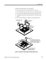
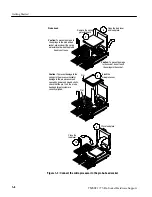
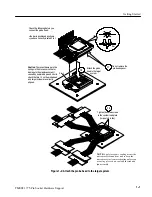
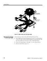
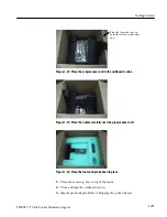
Follow the steps in Figures 1--2 through 1--4 to install the probe head.
Attach the custom
load plate.
4
5
Close the
load lever.
Target-system socket
1
Open and remove
your load plate.
Remove the
microprocessor from
the target system.
3
Open the
load lever.
2
Caution:
To prevent damage
to the socket, do not touch
the springs in the socket.
Note:
Load plates are vendor-specific.
Use the load plates marked with an F with
the Foxconn socket and the load plate
marked with a T with the Tyco socket.
Figure 1--2: Attach the custom load plate to the target-system socket
Содержание TMSST1
Страница 1: ...Instruction Manual TMSST1 775 Pin Socket Hardware Support 071 1315 00 www tektronix com ...
Страница 4: ......
Страница 8: ...Table of Contents iv TMSST1 775 Pin Socket Hardware Support ...
Страница 12: ...Service Safety Summary viii TMSST1 775 Pin Socket Hardware Support ...
Страница 15: ...Getting Started ...
Страница 16: ......
Страница 35: ...Specifications ...
Страница 36: ......
Страница 45: ...Reference ...
Страница 46: ......
Страница 49: ...Replaceable Parts List ...
Страница 50: ......
Страница 56: ...Replaceable Parts List 4 6 TMSST1 775 Pin Socket Hardware Support ...
Страница 57: ...Index ...
Страница 58: ......


