Getting Started
1--2
TMSST1 775-Pin Socket Hardware Support
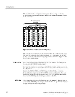
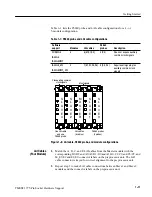
The modules must be configured and merged as shown in Figure 1--1. The
memory depth is chosen automatically based on the shallowest memory depth of
the four modules.
M
A
S
T
E
R
S
L
A
V
E
2
S
L
A
V
E
4
S
L
A
V
E
1
S
L
A
V
E
3
Most signals
Plus auxiliary common
clock signals
Figure 1--1: Master and Slave module configuration
The term
Master module
refers to the middle module of a 5-wide module merge.
The term Slave module refers to the modules to the left or right of the Master
module of a 4 or 5-wide module merge. Figure 1--1 shows the configuration for a
4- or 5-wide module merge.
You can use the TLA7AX, 450 MHz logic analyzer modules and P6860 probes
to connect to the TMSST1 probe adapter.
For more information on connecting your P6860 probes to the preprocessor unit,
see page 1--10.
Refer to the
P6810, P6860, and P6880 Logic Analyzer Probes Instruction
Manual
, Tektronix part number 071-1059-XX, for more information. You can
access this manual from the Tektronix.com web site. You can also find informa-
tion about the P6860 probes in the logic analyzer online help.
You can use the TLA7AX, 450 MHz logic analyzer modules, and LAI cables to
connect to the TMSST1 probe Adapter. The LAI cables are specifically designed
for use with the TMSST1 probe Adapter.
P6860 Probes
LAI Cables
Содержание TMSST1
Страница 1: ...Instruction Manual TMSST1 775 Pin Socket Hardware Support 071 1315 00 www tektronix com ...
Страница 4: ......
Страница 8: ...Table of Contents iv TMSST1 775 Pin Socket Hardware Support ...
Страница 12: ...Service Safety Summary viii TMSST1 775 Pin Socket Hardware Support ...
Страница 15: ...Getting Started ...
Страница 16: ......
Страница 35: ...Specifications ...
Страница 36: ......
Страница 45: ...Reference ...
Страница 46: ......
Страница 49: ...Replaceable Parts List ...
Страница 50: ......
Страница 56: ...Replaceable Parts List 4 6 TMSST1 775 Pin Socket Hardware Support ...
Страница 57: ...Index ...
Страница 58: ......


