background image

Optical Sampling Modules

4–96

CSA8000 & TDS8000 Instruments and Sampling Modules

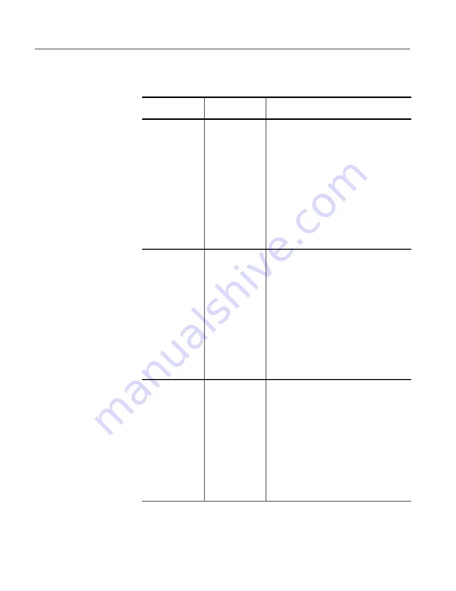
Table 4–9: Reference receiver frequency response limits 

Optical 
sampling module

Filter

Limits

80C01

OC-12/STM-4

(MHz)

(dB)

Frequency

Lower

Nominal

Upper

0.000

–0.50

0.00

+0.50

93.3

–0.61

–0.11

+0.39

186.6

–0.95

–0.45

+0.05

279.9

–1.52

–1.02

–0.52

373.2

–2.36

–1.86

–1.36

466.7

–3.50

–3.00

–2.50

559.9

–5.67

–4.51

–3.35

622.1

–7.25

–5.71

–4.17

653.2

–8.08

–6.37

–4.66

746.5

–10.74

–8.54

–6.35

839.8

–13.55

–10.93

–8.31

933.1

–16.41

–13.41

–10.41

1244.2

–26.11

–21.45

–16.78

80C01, 80C03

OC-48/STM-16

(MHz)

(dB)

Frequency

Lower

Nominal

Upper

0.000

–0.50

0.00

+0.50

373.3

–0.61

–0.11

+0.39

746.5

–0.95

–0.45

+0.05

1119.7

–1.52

–1.02

–0.52

1493.1

–2.36

–1.86

–1.36

1866.3

–3.50

–3.00

–2.50

2239.5

–5.67

–4.51

–3.35

2488.3

–7.25

–5.71

–4.17

2612.8

–8.08

–6.37

–4.66

2986.0

–10.74

–8.54

–6.35

3359.3

–13.55

–10.93

–8.31

3732.6

–16.41

–13.41

–10.41

4976.7

–26.11

–21.45

–16.78

80C01,

 80C02,

8

0C04, 80C05

OC-192/STM-64

(MHz)

(dB)

Frequency

Lower

Nominal

Upper

0.000

–0.85

0.00

+0.85

1493.2

–0.96

–0.11

+0.74

2986.0

–1.30

–0.45

+0.40

4478.8

–1.87

–1.02

+0.17

5972.4

–2.71

–1.86

–1.01

7465.0

–3.86

–3.00

–2.16

8958.0

–6.19

–4.51

–2.83

9953.28

–7.87

–5.71

–3.55

10451.2

–8.75

–6.37

–3.99

11944.0

–11.53

–8.54

–5.56

13437.2

–14.45

–10.93

–7.41

14930.4

–17.41

–13.41

–9.41

Содержание CSA8000 Series

Страница 1: ...Sampling Oscilloscope 071 0438 01 Warning The servicing instructions are for use by qualified personnel only To avoid personal injury do not perform any servicing unless you are qualified to do so Refer to all safety summaries prior to performing service www tektronix com ...

Страница 2: ... and foreign patents issued and pending Information in this publication supercedes that in all previously published material Specifications and price change privileges reserved Tektronix Inc P O Box 500 Beaverton OR 97077 TEKTRONIX and TEK are registered trademarks of Tektronix Inc ...

Страница 3: ...eturn of the product to Customer Customer shall be responsible for paying any associated taxes or duties This warranty shall not apply to any defect failure or damage caused by improper use or improper or inadequate maintenance and care Tektronix shall not be obligated to furnish service under this warranty a to repair damage resulting from attempts by personnel other than Tektronix representative...

Страница 4: ......

Страница 5: ...pling Modules 2 2 Connect the Peripherals 2 4 Power On the Instrument 2 5 Powering Off the Instrument 2 7 Software Installation 2 7 Description 2 7 Software Release Notes 2 8 Operating System Reinstallation 2 8 Windows 98 Reinstall Only 2 8 System Diagnostics 2 9 Operating Instructions 2 11 Documentation Map 2 12 User Interface Map Complete Control and Display 2 13 Front Panel Map Quick Access to ...

Страница 6: ... Optical Modules Test Record 4 28 Main Instrument 4 33 Prerequisites 4 33 Time interval accuracy short term optimized and locked to internal 10 MHz reference modes 4 34 External direct trigger level accuracy 4 37 External direct trigger sensitivity 4 40 External direct trigger delay jitter short term optimized and locked to internal 10 MHz reference modes 4 43 External prescaled trigger delay jitt...

Страница 7: ...venting ESD 6 1 Inspection and Cleaning 6 2 Interior Cleaning 6 2 Exterior Cleaning 6 2 Removal and Installation Procedures 6 7 Preparation 6 7 Procedures for External Modules 6 9 Procedures for Modules 6 21 Exchanging electrical sampling module 6 62 Troubleshooting 6 67 Service Level 6 67 Check for Common Problems 6 67 Equipment Required 6 70 Isolating Failures between the 80E0X 80C0X Modules or ...

Страница 8: ...nts and Sampling Modules Options and Accessories Standard Accessories 7 2 Optional Accessories 7 3 Options 7 4 Electrical Parts List Diagrams Symbols 9 16 Mechanical Parts List Parts Ordering Information 10 1 Using the Replaceable Parts List 10 2 ...

Страница 9: ...ure 4 7 Channel button location 4 13 Figure 4 8 Main time base verification 4 14 Figure 4 9 Mag time base verification 4 15 Figure 4 10 Time interval accuracy test hookup 4 34 Figure 4 11 External direct trigger test hookup 4 37 Figure 4 12 External direct trigger sensitivity test hookup 4 40 Figure 4 13 External direct trigger jitter test hookup 4 43 Figure 4 14 External prescaled test hookup 4 4...

Страница 10: ...te input from the pulse pattern generator Note the stable clock signal waveform Compare this with Figure 4 30 in which the clock signal is not synchronized 4 109 Figure 4 32 Example of the display zoomed in to 10 mV div and 10 ps div at the crossing point 50 on the recovered clock signal C3 4 110 Figure 4 33 80A00 test hookup 4 112 Figure 5 1 Adjustment setup using the DMM 5 3 Figure 5 2 Adjustmen...

Страница 11: ...ule door spring removal 6 56 Figure 6 33 Module slot door removal 6 57 Figure 6 34 Module ejector handles removal 6 59 Figure 6 35 Spring arm position 6 60 Figure 6 36 Electrical module hardware removal 6 61 Figure 6 37 Optical module cover removal 6 63 Figure 6 38 80A01 parts removal 6 64 Figure 6 39 Location of power on and over current LEDs 6 71 Figure 6 40 Location of debug pins 6 72 Figure 6 ...

Страница 12: ...13 80A01 block diagram 9 13 Figure 9 14 80C06 Optical sampling block diagram 9 14 Figure 9 15 80A01 block diagram 9 15 Figure 10 1 External parts 10 7 Figure 10 2 Front panel and drives 10 9 Figure 10 3 Power supply 10 11 Figure 10 4 Acquisition 10 13 Figure 10 5 Coaxial cables 10 15 Figure 10 6 Electrical modules 10 17 Figure 10 7 Optical modules 10 18 Figure 10 8 80A01 module 10 19 Figure 10 9 A...

Страница 13: ...Table 1 14 Electrical sampling modules Timebase system 1 15 Table 1 15 Electrical sampling modules Power consumption 1 15 Table 1 16 Electrical sampling modules Mechanical 1 16 Table 1 17 Optical modules Descriptions 1 17 Table 1 18 Optical modules Acquisition 1 18 Table 1 19 Optical modules Clock recovery option CR 1 32 Table 1 20 Optical modules Mechanical 1 34 Table 1 21 Optical modules Environ...

Страница 14: ...Clock recovery settings 4 107 Table 5 1 Adjustments required for module replaced 5 1 Table 5 2 Required equipment and materials 5 2 Table 6 1 External inspection check list 6 3 Table 6 2 Internal inspection check list 6 4 Table 6 3 Tools required for module removal 6 8 Table 6 4 Failure symptoms and possible causes 6 67 Table 6 5 Power supply voltages 6 73 Table 6 6 Action required for module repl...

Страница 15: ...s of the product ensure that the product is properly grounded Ground the Product The modules are indirectly grounded through the grounding conductor of the mainframe power cord To avoid electric shock the grounding conductor must be connected to earth ground Before making connections to the input or output terminals of the product ensure that the product is properly grounded Observe All Terminal R...

Страница 16: ...ions or practices that could result in injury or loss of life CAUTION Caution statements identify conditions or practices that could result in damage to this product or other property Terms on the Product These terms may appear on the product DANGER indicates an injury hazard immediately accessible as you read the marking WARNING indicates an injury hazard not immediately accessible as you read th...

Страница 17: ... this product unless another person capable of rendering first aid and resuscitation is present Disconnect Power To avoid electric shock switch off the instrument power then disconnect the power cord from the mains power Use Care When Servicing With Power On Dangerous voltages or currents may exist in this product Disconnect power remove battery if applicable and disconnect test leads before remov...

Страница 18: ...Service Safety Summary xiv CSA8000 TDS8000 Instruments and Sampling Modules ...

Страница 19: ...roductions provide important information needed to do the service correctly safely and efficiently Manual Conventions This manual uses certain conventions that you should become familiar with before attempting service Throughout this manual the term module appears A module is composed of electrical and mechanical assemblies circuit cards interconnecting cables and a user accessible front panel Sam...

Страница 20: ...number 071 0443 XX H CSA8000 TDS800 Reference manual Tektronix part number 071 0437 XX H 80E01 80E02 80E03 and 80E04 Electrical Sampling Modules User manual Tektronix part number 071 0434 XX H 80C00 Series Optical Sampling Modules User manual Tektronix part number 071 0435 XX H CSA8000 TDS800 Rackmount Kit Instructions Tektronix part number 071 0696 XX H 80A01 Trigger Prescale Preamplifier Module ...

Страница 21: ...om Sales support 1 800 833 9200 select option 1 Service support 1 800 833 9200 select option 2 Technical support Email techsupport tektronix com 1 800 833 9200 select option 3 1 503 627 2400 6 00 a m 5 00 p m Pacific time This phone number is toll free in North America After office hours please leave a voice mail message Outside North America contact a Tektronix sales office or distributor see the...

Страница 22: ...Preface xviii CSA8000 TDS8000 Instruments and Sampling Modules ...

Страница 23: ......

Страница 24: ..._ C H The instrument must have been operating continuously for 20 minutes within the operating temperature range specified H The instrument must be in an environment with temperature altitude humidity and vibration with the operating limits described in these specifications NOTE Sampling Interface refers to both the small module compartments and the large module compartments unless otherwise speci...

Страница 25: ...Short Term Optimized and Locked to 10 MHz Reference The 10 MHz reference may be internal or external n Time internal ac curacy short term optimized mode Strobe placement accuracy for a given horizontal interval and position on same strobe line per table below Contribution from 80E04 sampling module is included in specification Range Time Interval Accuracy 20 ps div 1 ps 1 of interval 21 ps div 8 p...

Страница 26: ... display Variable trigger hold off range and resolu tion Adjustable 5 ms to 50 ms in 0 5 ns increments When External Prescaled Trigger mode is used holdoff period applies to the Prescaled circuit output External direct trigger capabilities and conditions Direct edge triggering on signal applied to dedicated front panel connector with Holdoff Level Adjust Auto Normal High Frequency On Off and Enhan...

Страница 27: ...y Reject on Zero typical External direct trigger real time accessory interface Tekprobe SMA Levels 1 and 2 Hot switching is permitted on this real time accessory interface External prescaled trigger capabilities Prescaled triggering on signal applied to dedicated front panel connector with Holdoff Auto Normal Metastability Reject On Off External prescaled trigger specifications apply only under th...

Страница 28: ...rizontal position or better External prescaled delay jitter locked to internal 10 MHz refer ence mode Typical 1 6 ps RMS 0 05 ppm of horizontal position typical External prescaled trigger metastability Enhanced Triggering Metastability Reject on Zero typical Internal clock trigger rates Rate selectable at 25 50 100 and 200 kHz internally and is provided to the trigger to the TDR stimulus drives in...

Страница 29: ...et bulb temperature of 29 C at or below 60 C upper limits derates to 20 relative humidity at 60 C non condensing Altitude Operating 3 048 m 10 000 ft Nonoperating 12 190 m 40 000 ft Electrostatic dis charge susceptibility Up to 8 kV with no change to control settings or impairment of normal operation Up to 15 kV with no damage that prevents recovery of normal operation Table 1 5 CSA8000 and TDS800...

Страница 30: ...or on the rear panel Supports the following modes Standard mode output only Bi directional PS 2 compatible Bi directional Enhanced Parallel Port IEEE 1284 standard Mode 1 or Mode 2 v1 7 Bi directional high speed Extended Capabilities Port ECP Serial Port 9 pin D subminature serial port connector using NS16C550 compatible UARTs supporting transfer speeds up to 115 2 kbits sec PS 2 Keyboard and Mous...

Страница 31: ...and instrument setups Hard disk drive ca pacity 6 Gbytes Table 1 9 CSA8000 and TDS8000 Mechanical Specifications Characteristics Construction material Chassis Aluminum alloy Cosmetic covers PC ABS thermoplastic Front panel Aluminum alloy with PC thermoplastic overlay Module doors Nickel plated stainless steel Bottom cover Vinyl clad sheet metal Circuit boards Glass laminate Cabinet Aluminum Weight...

Страница 32: ... usually increase the horizontal timing jitter when external electromagnetic fields are applied For fields up to 3 V m the increase in the horizontal high frequency RMS jitter is typically less than 3 ps RMS of jitter added using the square root of the sum of the squares method An example follows If an 80C01 CR operating in clock recovery trigger mode exhibits 3 5 ps RMS of edge jitter with no EMC...

Страница 33: ...round and within a product Typically the internal environment inside a product is considered to be the same as the external Products should be used only in the environment for which they are rated Pollution Degree 1 No pollution or only dry nonconductive pollution occurs Products in this category are generally encapsulated hermetically sealed or located in clean rooms Pollution Degree 2 Normally o...

Страница 34: ...tempera ture between 20_ C and 30_ C H The oscilloscope must have been operating continuously for 20 minutes within the operating temperature range specified H The instrument must be in an environment with temperature altitude humidity and vibration within the operating limits described in these specifications NOTE Sampling Interface refers to both the electrical sampling module interface and the ...

Страница 35: ...rtical nondestruct range 2 Maximum Input Voltage 80E01 2 0 V DC peak AC 80E02 80E03 80E04 3 0 V DC peak AC Vertical number of digitized bits 14 bits full scale Vertical sensitivity range3 The range of available full scale input settings 10 mV to 1 V full scale Compensation temperature range 5_ C about temperature where compensation was performed If compartment is changed on the mainframe a samplin...

Страница 36: ...ion 10 5 or less for the first 300 ps following step transition 3 or less over the zone 300 ps to 5 ns following step transition 1 or less over the zone 5 ns to 100 ns following step transition 0 5 after 100 ns following step transition 80E01 3 or less over the zone 10 ns to 20 ps before step transition 12 5 or less for the first 300 ps following step transition 5 5 3 or less over the zone 300 ps ...

Страница 37: ...instrument Operation to instrument specification is not guarantied outside of the vertical operating range 3 Input Signal Ranges in IEEE std 1057 section 2 2 1 4 IEEE std 1057 section 4 8 2 Transition Duration of Step Response Calculated from 0 35 bandwidth risetime product 5 IEEE std 1057 section 4 6 Analog Bandwidth 6 IEEE std 1057 section 4 8 4 Overshoot and Precursors Step transition occurs at...

Страница 38: ...ical for the first 400 ps following step transition 3 or less over the zone 400 ps to 5 ns following step transition 1 or less after 5 ns following step transition 1 IEEE std 1057 section 4 8 2 transition duration of step response 2 IEEE std 1057 section 4 8 4 overshoot and precursors Table 1 14 Electrical sampling modules Timebase system Specifications Characteristics Sampling rate DC 200 kHz max...

Страница 39: ...d 80E04 0 4 kg 13 oz Overall dimensions Height 25 mm 1 0 in Width 79 mm 3 1 in Depth 135 mm 5 3 in Does not include connectors connector savers connector covers push buttons or lock down hardware protruding from the front or rear panels Construction material Chassis aluminum alloy Front panel plastic laminate Circuit boards glass laminate Cabinet sleeve aluminum Cabinet end covers aluminum ...

Страница 40: ...st have been operating continuously for 20 minutes within the operating temperature range specified H The instrument must be in an environment with temperature altitude humidity and vibration within the operating limits described in these specifications NOTE Sampling Interface refers to both the electrical sampling module interface and the optical module interface unless otherwise specified Table ...

Страница 41: ...mplified O E converter with maximum optical bandwidth in combination with the internal electrical sampler u40 GHz Calibrated only at 1550 nm There is one reference receiver setup selectable OC 192 for 9 95328 Gb s Sonet SDH standards No clock recovery option available 80C06 Long wavelength 1520 nm 1580 nm Unamplified O E converter with maximum optical bandwidth in combination with the internal ele...

Страница 42: ...r 10 mW peak power at wavelength with highest relative responsively 80C05 10 mW average power 30 mW peak power at wavelength with highest relative responsively 80C06 20 mW average power 60 mW peak power at wavelength with highest relative responsively Effective wavelength Module Range range3 typical 80C01 1100 nm to 1650 nm 80C02 1100 nm to 1650 nm 80C03 700 nm to 1650 nm 80C04 1100 nm to 1650 nm ...

Страница 43: ... settings 25 mW 4 vertical offset To achieve these levels perform a dark level compensation keep the trigger rate and vertical offset the same as during the compensation and if the ambient temperature changes more than 1 C perform another dark level compensation Main instrument display vertical scale factors Module Maximum Minimum 80C01 1 mW per division 10 mW per division 80C02 1 mW per division ...

Страница 44: ... GHz setting 25 mW 4 of vertical value vertical offset 30 GHz setting 25 mW 6 of vertical value vertical offset 80C03 all settings 25 mW 2 of vertical value vertical offset 80C04 10 66 Gb s 25 mW 2 of vertical value vertical offset OC 192 STM 64 25 mW 2 of vertical value vertical offset 20 GHz setting 25 mW 4 of vertical value vertical offset 30 GHz setting 25 mW 6 of vertical value vertical offse...

Страница 45: ...ing Valid for calibrated wavelengths and for user calibration Offset capabilities Open loop User assigned fixed offset value applied to channel n Minimum optical bandwidth5 80C01 module 20 GHz setting 12 5 GHz setting u20 GHz u12 5 GHz 80C02 module 30 GHz setting 80C02 CR 30 GHz setting 80C02 and 80C02 CR 30 GHz setting 80C02 20 GHz setting 80C02 CR 12 5 GHz setting u30 GHz typical u29 GHz typical...

Страница 46: ... 20 GHz setting t25 ps 80C02 module 30 GHz setting t16 ps 20 GHz setting t25 ps 12 5 GHz setting t40 ps OC 192 STM 64 setting 47 ps 10 ps 80C03 module FC1063 setting 440 ps 35 ps GBE setting 373 ps 30 ps OC 48 STM 16 setting 187 ps 15 ps 80C04 module 30 GHz setting t16 ps 20 GHz setting t25 ps 10 66 Gb s setting t44 ps 10 ps OC 192 STM 64 setting 47 ps 10 ps 80C05 module 20 GHz setting t12 ps 30 G...

Страница 47: ...STM 64 setting t10 12 5 GHz setting t10 20 GHz setting t15 t5 mWpp except 80C03 t200 mWpp 80C02 OC 192 STM 64 setting t10 all typical 12 5 GHz setting t15 20 GHz setting t20 30 GHz setting t30 80C03 All settings t5 p to p typical 80C04 OC 192 STM 64 setting t10 all typical 10 66 Gb s setting t10 20 GHz setting t20 30 GHz setting t30 80C05 OC 192 setting t5 2 5 typical 20 GHz setting t10 5 typical ...

Страница 48: ...mWrms 20 GHz setting t25 mWrms t15 mWrms 80C02 module OC 192 STM 64 setting t10 mWrms t6 mWrms 12 5 GHz setting t10 mWrms t6 mWrms 20 GHz setting t15 mWrms t10 mWrms 30 GHz setting t30 mWrms 6 t20 mWrms 80C02 CR module OC 192 STM 64 setting t12 mWrms t7 mWrms 12 5 GHz setting t12 mWrms t7 mWrms 20 GHz setting t20 mWrms t15 mWrms 30 GHz setting t40 mWrms 6 t30 mWrms 80C03 80C03 CR modules FC1063 se...

Страница 49: ...92 mWrms t150 mWrms n OC 12 STM 4 622 Mb s Reference Receiver setting frequency response6 In the 622 08 Mb s NRZ setting the scalar frequency response is verified to fall within fourth order Bessel Thompson reference receiver boundary limits The OC 12 STM 4 nominal scalar frequency response matches the ITU 622 08 Reference Receiver Nominal curve with the following tolerance MHz dB Frequency Lower ...

Страница 50: ...ary limits are described in ITU T G 957 Tables I 1 and I 2 For convenience the scalar frequency response of the output amplitude for sinusoidal swept optical input has been interpreted from the Bessel Thompson transfer function and listed below MHz dB Frequency Lower Nominal Upper 0 000 0 50 0 00 0 50 373 3 0 61 0 11 0 39 746 5 0 95 0 45 0 05 1119 7 1 52 1 02 0 52 1493 1 2 36 1 86 1 36 1866 3 3 50...

Страница 51: ...e receivers San Antonio ITU Study Group 15 February 2000 These specifications are used to establish system interoperability and test conformance of optical interfaces to draft ITU T Recommendation G 691 which is scheduled to be completed in April 200 see ITU table A 1 G 691 from the WD 16 48 document from Study Group 15 dated February 2000 For convenience the scalar frequency response of the outpu...

Страница 52: ...e receiver has a nominal 3dB response at 0 75 9 95328GHz 7 465GHz This 10 66GByte reference receiver has a nominal 3dB response at 10 664 9 95328 7 465GHz 7 998GHz For convenience the scalar frequency response of the output amplitude for sinusoidal swept optical input has been interpreted from the published Bessel Thompson transfer function the frequencies scaled as described above and then listed...

Страница 53: ...2 1 02 0 52 1500 2 36 1 86 1 36 1875 3 50 3 00 2 50 2250 5 67 4 51 3 35 2500 7 25 5 71 4 17 2625 8 08 6 37 4 66 3000 10 74 8 54 6 35 3375 13 55 10 93 8 31 3750 16 41 13 41 10 41 5000 26 11 21 45 16 78 n GBE 1 25 Gb s Reference Receiver setting frequency response6 Scalar frequency response falls within Industry Standard Bessel Thompson reference receiver boundary limits 1 250 Gb s frequency respons...

Страница 54: ...destructive levels may exceed saturation and compression limits of the module 3 The optical wavelengths that the product accepts optical inputs and still provides a reasonable 25 of peak optimum wavelength conversion gain 4 Vertical accuracy specifications are referenced to the internal optical power meter reading for a given optical input and are limited to a temperature range within 5_ C of prev...

Страница 55: ...d 1s and multi consecutive mark sequences that is 2 3 4 and so forth logical 1s in a consecutive row NOTE a fixed pattern of 10101010 does not meet that requirement the 80C02 CR clock recovery function may not properly lock to such a pattern The 80C02 CR will however typically lock to a 11001100 pattern this is equivalent to a 2 48832 GHz optical square wave nOptical sensitivity range clock recove...

Страница 56: ...o 30 dBm typical 80C05 13 dBm to 21 dBm typical 80C06 13 dBm to 21 dBm typical Optical power meter accuracy typical 5 of reading connector uncertainty at the calibrated wavelengths See Table 1 18 page 1 18 1 These powers are the average optical input coupled into the external Optical Sampling Module optical input connector The range is defined for recovered clock and data with a resulting BER of 1...

Страница 57: ...orm may normally exhibit slightly more than 1 ps RMS jitter w sum of squares Ǹ Table 1 20 Optical modules Mechanical Name Characteristics Construction material Chassis parts constructed of aluminum alloy front panel constructed of plastic laminate circuit boards constructed of glass laminate Cabinet is aluminum Weight 80C01 1 13 kg 2 5 lbs 80C01 CR 1 34 kg 2 95 lbs 80C02 0 95 kg 2 1 lbs 80C02 CR 1...

Страница 58: ...led and operating 20 to 80 relative humidity with a maximum wet bulb temperature of 29_ C at or below 40_ C upper limit derates to 45 relative humidity at 40_ C non condensing Reference receivers frequency response tolerances 20_ C to 30_ C Optical power meter accuracy 20_ C 80 RH to 30_ C 80 RH Installed and non operating 5 to 90 relative humidity with a maximum wet bulb temperature of 29_ C at o...

Страница 59: ...80C00 Modules Specifications 1 36 CSA8000 TDS8000 Instruments and Sampling Modules back ...

Страница 60: ...hin the operating limits described in these specifications The 80A01 Trigger Prescale Preamplifier module is a single channel 8 14 GHz AC coupled limiting preamplifier It increases the trigger sensitivity of the 8000 Series instruments to v200 mVpk pk up to 12 5 GHz typical Table 1 22 Module characteristics Specifications Characteristics Mainframe interface Tekprobe Sampling Level 3 Hot switching ...

Страница 61: ...ument 3 Amplifier functions to 14 GHz but prescale trigger is nominally limited to 12 5 GHz for 200 mVpk pk sensitivity Table 1 23 Environmental specifications Specification Characteristics Temperature Operating 10 C to 40 C Humidity Non operating 5 to 90 relative humidity Operating 20 to 80 relative humidity Table 1 24 Mechanical specifications Specifications Characteristics Weight 0 37 kg 13 oz ...

Страница 62: ...standards Emissions European Community Requirements including EN 61326 EN55011 Class A Radiated Emissions EN55011 Class A Conducted Emissions IEC 1000 3 2 Power Harmonic Current Emissions Susceptibility The instrument meets or exceeds the EMC requirements of the following standards EN61326 1 European Community Requirements IEC 1000 4 2 Electrostatic Discharge Immunity 4 kV contact discharge 8 kV a...

Страница 63: ...80A01 Module Specifications 1 40 CSA8000 TDS8000 Instruments and Sampling Modules ...

Страница 64: ......

Страница 65: ...H Software Installation on page 2 7 Check the Environmental Requirements Read this section before attempting any installation procedures This section describes site considerations power requirements and ground connections for your instrument The instrument is designed to operate on a bench or on a cart in the normal position on the bottom feet For proper cooling at least two inches 5 1 cm of clear...

Страница 66: ...g module user manuals Read these manuals for instructions on how to install your sampling modules and then install them as outlined Sampling modules do not ship preinstalled NOTE To find sampling module user manuals check in the appendices of the CSA8000 TDS8000 User Manual if user documentation is available Users are instructed to insert their sampling module user manuals there NOTE After first i...

Страница 67: ...ingle large module in either compartment disables the first small module compartment This configuration see Figure 2 2 bottom configuration limits the input count to seven one from the large six from the small compartments Eight channels Two large modules and three small modules CH 1 CH 2 N A 1 CH 6 CH 3 CH 8 CH 5 CH 7 N A CH 4 CH 1 CH 2 CH 6 CH 3 CH 8 CH 5 CH 7 N A CH 4 N A Eight channels No larg...

Страница 68: ...n page 2 7 Table 2 1 Additional accessory connection information Item Description Monitor If you use a non standard monitor you may need to change the the Windows 98 display settings to achieve the proper resolution for your monitor Printer Connect the printer to the EPP enhanced parallel port connector directly If your printer has a DB 25 connector use the adapter cable that came with your printe...

Страница 69: ...uct ships with a USB keyboard that plugs into the USB port and a USB mouse that plugs into the back of the keyboard Figure 2 3 Locations of peripheral connectors on rear panel Power On the Instrument Follow these steps to power on the instrument for the first time 1 Check that the line fuses are correct for your application Both fuses must be the same rating and type Fuse types require a unique ca...

Страница 70: ...use that ships with the instrument Both can be plugged or unplugged without first turning power off 2 Connect the keyboard and mouse observing the caution above Note that the instrument ships with a USB keyboard which plugs into the USB port see Figure 2 3 on page 2 5 for location and a USB mouse which plugs into the back of the USB keyboard NOTE Connection of the keyboard and mouse is optional Yo...

Страница 71: ...8 before using the On Standby button To completely remove power to the instrument first soft power down the instrument using the On Standby button and then set the power switch on the rear panel to off You can restore the UI application to the screen by clicking its button in the Windows Task bar Software Installation This section describes how to install the system software found on the CSA8000 T...

Страница 72: ...ild CD After installation you can also read the copy from a directory on the product C Programs Files TDSCSA8000 System Use the following procedure if reinstalling Windows 98 becomes necessary NOTE Only do the reinstall if Windows 98 is missing or corrupted There are two possibilities for reinstall H The instrument can reboot from the hard drive if so reinstall windows using the emergency startup ...

Страница 73: ...rn the hard disk to the its original condition present when the instrument shipped Since data and programs you may have installed are lost with this rebuild you should do the Windows 98 Reinstall Only procedure instead if you can See Windows 98 Reinstall Only on page 2 8 If you must rebuild the system hard drive use the System Rebuild CD that shipped with the instrument Follow the instructions in ...

Страница 74: ...Installation 2 10 CSA8000 TDS8000 Instruments and Sampling Modules ...

Страница 75: ...integrated into the service procedures found in later sections of this manual For instance the procedures found in the section Performance Verification contain instructions for making the front panel settings required to check each instrument characteristic included there Also the general instructions for operating these instrument s internal diagnostic routines are found in Section 6 Maintenance ...

Страница 76: ... about the Sampling Modules Electrical or Optical Sampling Module User Manual1 ÎÎÎ ÎÎÎ ÎÎÎ ÎÎÎ ÎÎÎ ÎÎÎ ÎÎÎ ÎÎÎ ÎÎÎ ÎÎÎ ÎÎÎ ÎÎÎ ÎÎÎ ÎÎÎ ÎÎÎÎ ÎÎÎÎ ÎÎÎÎ ÎÎÎÎ ÎÎÎ ÎÎÎ ÎÎÎ ÎÎÎ ÎÎÎ ÎÎÎ ÎÎÎ ÎÎÎ ÎÎÎ ÎÎÎ ÎÎÎ Read these manuals for complete information about the sampling modules you purchased how to install them in the instrument how to use them and how to protect them from ESD Depending on the modules orde...

Страница 77: ...ath waveforms display here along with cursors masks etc to analyze them Readouts Display up to five readouts in this area selectable from the Readout Bar Controls Bar Quick access to waveforms and timebases for display and to their scale offset and position controls for adjustment Waveform Bar Access to waveform selection click waveform position drag and waveform properties right click A Readout R...

Страница 78: ...trols based on selected channels Press to quickly return to instrument default control settings Turn knobs to vertically scale position and offset selected waveform Press to display and select a time base view not selected or to select among displayed views press selected timebase again to toggle it off except Main which is always on Turn knobs to Horizontally scale position and set record length ...

Страница 79: ...icon to add offset to a waveform Drag the Waveform Icon vertically to position waveform Drag the Horizontal Reference to move the point around which horizontal scaling expands and contracts the waveforms Front Panel I O Map Floppy disk drive accessible from Windows 98 Compartments for large modules up to two channels Compartments for small modules up to eight channels ANTISTATIC CONNECTION for wri...

Страница 80: ...nnector for mouse or keyboard and mouse COM1 serial port Upper VGA port to connect a second monitor for side by side display Lower VGA port to connect a monitor for oscilloscope display PS 2 connectors for mouse and keyboard Parallel port Centronics to connect printer or other device GPIB port to connect to controller Card Bus slots for two PCMCIA type 1 cards two type 2 cards or one type 3 card C...

Страница 81: ...e 2 1 ÎÎÎ ÎÎÎ ÎÎÎ ÎÎÎ ÎÎÎ ÎÎÎ ÎÎÎ ÎÎÎ ÎÎÎ ÎÎÎ For a brief description of controls 2 Move your mouse pointer and let it rest over a control that is a menu name a menu item tool bar button tool bar readout etc When you perform this step the help system pops up a short definition or a label of the control See right For a more robust description 3 Click the What s This button in the main display or in...

Страница 82: ...elements resources To use the online help Cont For in depth contextual overviews 5 Most dialog boxes whether setup or other types have a Help button as shown right Click the button to open the help system with an overview of the dialog box that s currently displayed See below Click or touch here ...

Страница 83: ...ch for in depth help using methods with which most users of PCs are familiar from the application menu bar select Help and then select Contents Index See right 7 From the online help finder see below choose from the three tabs 8 Click the book icons to expose topic titles and then click a topic to highlight it Click the Display button to open the topic in a help window ...

Страница 84: ...ocedures 9 You can display step by step setup instructions for setups you want to make From the application menu bar select Help and then select Setup Guide See right 10 Select a procedure from the list that displays The procedure will display in a help window that is sized and located to minimize interference with the controls needed to perform it See below ...

Страница 85: ...ne finder you may want to enable full text search From the application menu bar select Help and then select Contents Index See right 12 From the online help finder see below choose the Find tab 13 Choose the method for word list generation and select next or finish Once the word list generation finishes future accesses of the find tab will immediately access a pane for searching with full text sea...

Страница 86: ...op up the Start menu and then select Help from the menu See lower right The online help for the Windows operating system displays 16 When your done with the online help you can dismiss it To restore the user interface application to the screen click its icon in the tool bar Tip To switch between online help and the applica tion you can hold down the ALT key while you press Tab repeatedly to altern...

Страница 87: ...ling modules follow the precautions described in this manual and the manuals accompanying your instrument Always use a wrist strap provided with your instrument when handling sampling modules or making signal connections The input circuitry in your sampling module is very susceptible to damage from overdrive signals and electrostatic discharge Never apply a DC or peak voltage greater than the Maxi...

Страница 88: ...tors on the sampling module to make connections to the device under test Each channel has a SELECT channel button and a yellow channel light The button operates as follows H If the yellow channel light is on the channel is acquiring a waveform H If you press the button and the channel is not currently being acquired for any channel or math waveform then the instrument activates turns on the channe...

Страница 89: ...the sampling optical in a secure location when not in use Replace the protective cap on the input connector when the sampling optical is not in use To prevent loss of optical power or damage to the optical connectors keep the connectors clean at all times Also insure that all connectors and jumpers attached to the inputs are clean prior to insertion To keep the optical input power to an appropriat...

Страница 90: ...R shown The optical input connector uses a universal connector interface UCI that allows use of many standard fiber optic female connector styles Some of the standard UCI interfaces supported are FC ST SC and DIN Refer to a current Tektronix catalog for details Optional clock and data recovery circuitry provides clock and data outputs the recovered clock is also internally routed to the main instr...

Страница 91: ...vity of the prescale trigger input of these oscilloscopes to v200 mVpk pk CAUTION To prevent damage to your module or instrument do not apply a signal outside the Maximum Input Voltage Swing for your module To prevent electrostatic damage to the instrument and sampling modules follow the precautions described in this manual and the manuals accompanying your instrument Always use a wrist strap prov...

Страница 92: ...g Modules Connect a trigger signal that you need to preamplify to the input connector Connect the preamplified output signal from the output connector to the prescale trigger input of the oscilloscope Connector Care Refer to Connector Care on page 2 24 Signal Connector ...

Страница 93: ......

Страница 94: ...t touch screen and user front panel with direct access to commonly used scope functions The instrument is also equipped with a mouse pointing device to facilitate access to more advanced scope functions A signal enters the instrument through a direct coaxial connection to the input connector on a sampling module or a real time probe connected to the sampling module channel Acquisition System The a...

Страница 95: ...eir settings are reported to the processor system The front panel board also turns the LEDs on and off and generates the bell signal Front panel menu switches are also read by the PPC processor board The processor sends any changes in menu selections to the processor system The ON STBY switch is one of the menu switches However it is not read by the front panel board but passes through the front p...

Страница 96: ...he sampling coincidence between channels is very close Acquisition deskew function is carried out by making separate acquisitions over individual acquisition windows For the 80E01 an individual strobe delivered from the instrument mainframe to the acquisition channel controls the timing of the strobe assertion to the channel Acquisition deskew function is carried out by moving the strobe timing fo...

Страница 97: ...pling module Settings derived from this reference are stored in a non volatile EEPROM in the sampling module although the responsibility for the execution of these settings is with the mainframe When used in the acquisition mode that is with the TDR step generator turned off each channel functions as a normal sampling input Both channels are strobed simultaneously from a single strobe generator co...

Страница 98: ... optical impulse applied to the front panel connector This insures that all components are included but also means that components can not be replaced without performing calibration Compensation performs a DC transfer curve characterization for each bandwidth reference receiver setting The curve data is stored in the module s EEPROM and used to generate a look up table in the mainframe This data c...

Страница 99: ...eiver calibration is performed with a sub picosecond and optical impulse and a fourier transform method H OC12 The electrical sampler is adjusted to approximately 7 5 GHz 3dB bandwidth and signal is routed through a hardware filter designed to result in the combined system having an OC12 STM 4 Reference Receiver response H OC48 The electrical sampler is adjusted to 7 5 GHz 3dB bandwidth and signal...

Страница 100: ...C03 module supports conformance testing of both short and long bandwidth 700 1650 nm signals at 1 063 1 250 and 2 488 Mbps as well as general purpose testing with up to 2 3 GHz optical bandwidth Its amplified optical to electrical converter design enables the user to examine very low level optical signals H OC48 The electrical sampler is adjusted to approximately 12 5 GHz 3dB bandwidth and signal ...

Страница 101: ...mized during the calibration such that the combined system will have an OC192 STM 64 or 10 66 Gb Reference Receiver response H 20 GHz The sampler bandwidth and response is set during the calibration such that the combined system will have an Optical Bandwidth 6dB 20 GHz H 30 GHz The sampler bandwidth and response is set during the calibration such that the combined system will have an Optical Band...

Страница 102: ... page 9 14 The 80A01 module is designed to increase the sensitivity of the prescale trigger input of the CSA8000 TDS8000 instruments to v200 mVpk pk The major function block of the module an high sensitivity high gain RF amplifier The input and output to this amplifier are routed to two identical SMA female connectors labelled Input and Output at the module front panel The module receives power fr...

Страница 103: ...Theory of Operation 3 10 CSA8000 TDS8000 Instruments and Sampling Modules ...

Страница 104: ......

Страница 105: ...heck functionality first do the procedures just mentioned and then do the procedure Perform the Functional Tests found under Brief Procedures on page 4 7 Advantages These procedures require minimal additional time to perform require no additional equipment other than connection hardware and more completely test the internal hardware of the instrument They can be used to quickly determine if the in...

Страница 106: ...Performance Verification Procedures 4 2 CSA8000 TDS8000 Instruments and Sampling Modules ...

Страница 107: ...age 4 1 for information on when to use these procedures Perform the Diagnostics Do the following steps to run the internal routines that confirm basic functional ity and proper adjustment Equipment required None Prerequisites First all sampling modules to be diagnosed must be installed as outlined in their user manuals Second power on the instrument and allow a 20 minute warm up before doing this ...

Страница 108: ...n the Run box leave Loop and Halt on Failure unchecked 3 Verify that the diagnostic suite passes a Click the Run button to execute the diagnostics b The diagnostics may take several minutes to complete Verify that Pass appears as Status in the dialog box when the diagnostics complete c If instead an error number appears as Status rerun the diagnostics If Fail status continues after rerunning compe...

Страница 109: ...nstalled Prerequisites First all sampling modules to be diagnosed must be installed as outlined in their user manuals Second power on the instrument and allow a 20 minute warm up before doing this procedure 1 Run the compensation routines a From the application menu bar select Utilities and then select Com pensation In the Compensation dialog box the main instrument mainframe and sampling modules ...

Страница 110: ...wing these instructions NOTE Failing to install the 50 ohm terminations on 80E00 sampling module input connectors can yield erroneous compensation failures or results 2 Verify that the compensation routines pass a The compensation may take several minutes to complete Verify that Pass appears as Status for the main instrument and for all sampling modules listed in the Compensation dialog box when c...

Страница 111: ...horizontal divisions as limits STOP DO NOT make changes to the front panel settings that are not called out in the procedures Each verification procedure will require you to set the instrument to default settings before verifying functions If you make changes to these settings other than those called out in the procedure you may obtain invalid results In this case go back to step 1 and repeat the ...

Страница 112: ...re 4 2 Hookup for electrical functional tests 4 Set the DC CALIBRATOR OUTPUT a Push the Vertical MENU front panel button This displays the Vert Setup dialog box b Enter a level of 200 mV in the DC CAL box c Push the Vertical MENU front panel button again to dismiss the Vert Setup dialog box 5 Select the channel to test Push the channel button for the channel you want to test The button lights and ...

Страница 113: ... dialog box Click each of the three acquisition modes and confirm that the following statements are true H Sample mode displays an actively acquiring waveform on screen Note that there is a small amount of noise present on the DC level H Average mode displays an actively acquiring waveform on screen with the noise reduced H Envelope mode displays an actively acquiring waveform on screen with the u...

Страница 114: ...hannel is operational Confirm that the following statements are true H The vertical scale readout for the channel under test shows a setting of 1 mW and a baseline trace at about center screen See Figure 4 5 on page 4 11 H Turning the Vertical OFFSET front panel knob counterclockwise offsets the baseline towards the bottom of the screen turning the knob clockwise offsets the baseline towards the t...

Страница 115: ...the three acquisition modes and confirm that the following statements are true H Sample mode displays an actively acquiring waveform on screen Note that there may be a small amount of noise present on the baseline level H Average mode displays an actively acquiring waveform on screen with any noise present reduced H Envelope mode displays an actively acquiring waveform on screen with the upper and...

Страница 116: ...ut channel as shown in Figure 4 6 CSA8000 TDS8000 SMA cable from INTERNAL CLOCK output to 80E00 C3 input 10x attenuator Figure 4 6 Hookup for the time base tests 3 Set up the instrument a Push the Trigger MENU front panel button to display the Trig Setup dialog box b Click Internal Clock under Trigger Source in the Trig Setup dialog box The Internal Clock rate should be set to 200kHz c Push the Tr...

Страница 117: ...mperatures there may be extraneous data points beyond the first half cycle when viewing the front panel Internal Clock output as is done in this step This behavior may also occur when viewing multiple cycles in TDR mode In both cases this behavior is normal H Rotating the Horizontal SCALE knob clockwise expands the waveform on screen more horizontal divisions per waveform period counter clockwise ...

Страница 118: ...ime base view 7 Verify that the Mag1 time base operates Confirm the following statements H The brackets on the Main View waveform top graticule are a full screen width apart 10 divisions See Figure 4 9 on page the 4 15 H One period of the internal clock signal a square wave in the Mag view bottom graticule is about five horizontal divisions on screen Matches the waveform in the top graticule See F...

Страница 119: ...ional Test Procedures Perform the Hardware and Operating System Tests These procedures verify the instrument hardware functions A diagnostics program called QAPlus Win is used to make the verifications No equipment is required QAPlus WIN is a comprehensive software application used to check and verify the operation of the PC hardware in the portable mainframe This procedure use QAPlus WIN in to ru...

Страница 120: ...e results of the test Bad sectors on your hard drive are still found and marked H The installation program for QAPlus WIN stalls at the end of installation To continue after the installation stalls press CTRL ALT DEL highlight the QAPlus WIN installation program and then click End Task H The QAPlus WIN keyboard test does not respond correctly to keys used by Windows 98 Keyboards made for use with ...

Страница 121: ...the Start Menu Finally click QAPlus_Win 3 Click the Quick Test button to run the diagnostics suite a Follow any instructions appearing on screen Ignore nonapplicable tests for example ignore any Media tests that check speakers and wav audio files b When testing completes several minutes proceed to step 4 4 Check test results in scrollable results listing in the lower left corner of the QAPlus test...

Страница 122: ...Brief Procedures 4 18 CSA8000 TDS8000 Instruments and Sampling Modules ...

Страница 123: ...cedure Perform the Diagnos tics found on page 4 3 and the procedure Perform the Functional Tests found on page 4 7 H A compensation must have been done within the recommended calibration interval and at a temperature within 2_ C of the present operating tempera ture If at the time you did the procedures Perform the Diagnostics and Perform the Functional Tests you also did the Perform the Compensat...

Страница 124: ... short circuit 3 5 mm SMA male Tektronix Part number 015 1020 01 13 Synthesized signal generator Signal generator 50 MHz to 50 GHz Anritsu Wiltron 69187B 14 Power meter 80E01 only Power meter Anritsu Wilton ML2437A 15 Power sensor 80E01 only Power sensor w attached cable Anritsu Wilton ML2425A 16 Adapter 80E01 only 2 4 mm male to male connectors HP11900A 17 Adapter 80E01 only 2 4 mm female to fema...

Страница 125: ...number or model Minimum requirements 30 Cable fiber optic Qt 2 Single mode 2 m FC PC to FC PC Tektronix part number 174 1910 00 31 Cable coaxial 80A01 only Qt 2 50 W 4 ns delay with SMA male at each end Tektronix Part number 015 0561 00 32 Cable coaxial 80A01 only 50 W 1 ns delay with SMA male at each end Tektronix Part number 015 0562 00 ...

Страница 126: ...Performance Tests 4 22 CSA8000 TDS8000 Instruments and Sampling Modules ...

Страница 127: ...ain frame H 80E00 Electrical Sampling Modules Checks all supported models of electrical sampling modules H 80C00 Optical Sampling Modules Checks all supported models of optical sampling modules H 80A01 Trigger Prescale Limiting Preamplifier Module Checks the module listed left Do not enter values into these records rather make copies of the records and enter test results on the copies The test rec...

Страница 128: ... 1 ms 0 991 ns 0 991 ns 0 991 ns 1 009 ns 1 009 ns 1 009 ns Time interval accuracy locked to internal 10 MHz reference mode Horizontal Position Set to 19 ns 100 ns 1 ms 0 9919 ns 0 9919 ns 0 9919 ns 1 0081 ns 1 0081 ns 1 0081 ns External direct trigger delay jitter short term optimized mode Horizontal Position Set to 19 ns 100 ns 1 ms none none none 1 5 ps 2 5 ps 11 5 ps External direct delay jitt...

Страница 129: ...oming Outgoing Maximum Input Impedance C1 Impedance Baseline 80E04 only 49 5 W 1 mV 50 5 W 1 mV C2 Impedance Baseline 80E04 only 49 5 W 1 mV 50 5 W 1 mV DC Voltage accuracy single point within 5_C of compensated temperature C1 100 mV diV Input level Offset 1100 mV 1550 mV Offset 1100 mV 1350 mV Offset 1100 mV 1100 mV Offset 1100 mV 850 mV Offset 1100 mV 650 mV Offset 0 mV 450 mV Offset 0 mV 250 mV...

Страница 130: ... mV 9 7 mV 14 7 mV 18 7 mV 18 7 mV 14 7 mV 9 7 mV 14 7 mV 18 7 mV 11 mV 7 mV 2 mV 7 mV 11 mV 18 7 mV 14 7 mV 9 7 mV 14 7 mV 18 7 mV DC Vertical Voltage deviation from linear least squares fit C1 Set the Vin 450 mV 350 mV 250 mV 150 mV 50 mV 50 mV 150 mV 250 mV 350 mV 450 mV 10 mV 10 mV 10 mV 10 mV 10 mV 10 mV 10 mV 10 mV 10 mV 10 mV 10 mV 10 mV 10 mV 10 mV 10 mV 10 mV 10 mV 10 mV 10 mV 10 mV DC Ve...

Страница 131: ... set to set to none none 35 ps 35 ps C2 TDR Polarity set to set to none none 35 ps 35 ps TDR system step response aberrations 80E04 models only C1 positive polarity zone from 10 ns to 20 ps2 from 400 ps to 5 ns3 from 5 ns on3 3 3 1 3 3 1 C1 negative polarity zone from 10 ns to 20 ps2 from 400 ps to 5 ns3 from 5 ns on3 3 3 1 3 3 1 C2 positive polarity zone from 10 ns to 20 ps2 from 400 ps to 5 ns3 ...

Страница 132: ... Test Minimum Incoming Outgoing Maximum Dark level C1 at 100 mW 80C01 OC 12 STM 4 OC 48 STM 16 OC 192 STM 64 12 5 GHz 20 GHz 80C02 OC 192 STM 64 12 5 GHz 20 GHz 30 GHz 80C04 OC 192 STM 64 FEC10664 20 GHz 30 GHz C1 at 5 mW 80C03 FC1063 GBE OC 48 STM 16 C1 at 100 mW 80C05 OC 12 STM 4 20 GHz 30 GHz 40 GHz C1 at 200 mW 80C06 50 GHz 10 mW 10 mW 10 mW 10 mW 10 mW 10 mW 10 mW 10 mW 10 mW 10 mW 10 mW 10 m...

Страница 133: ...E Clock Recovery OC 48 STM 16 Clock Recovery C1 at 100 mW 80C05 OC 192 STM 64 Clock Recovery 20 GHz Clock Recovery 30 GHz Clock Recovery 40 GHz Clock Recovery C1 at 200 mW 80C06 50 GHz Clock Recovery none none none none none none none none none none none none none none none none none none none none none none none none none none none none none none none none none none none none none none none none ...

Страница 134: ...cy MHz 0 000 Nominal response dB 0 00 93 3 0 11 186 6 0 45 279 9 1 02 373 2 1 86 466 7 3 00 559 9 4 51 622 1 5 71 653 2 6 37 746 5 8 54 839 8 10 93 933 1 13 41 1244 2 21 45 0 50 0 61 0 95 1 52 2 36 3 50 5 67 7 25 8 08 10 74 13 55 16 41 26 11 0 50 0 39 0 05 0 52 1 36 2 50 3 35 4 17 4 66 6 35 8 31 10 41 16 78 OC48 STM 16 2 488 Gb s Reference Receiver setting frequency response 80C01 and 80C03 module...

Страница 135: ...6 7 41 9 41 FC10664 Reference Receiver setting frequency response 80C04 module only Frequency MHz 0 000 Nominal response dB 0 00 1493 2 0 11 2986 0 0 45 4478 8 1 02 5972 4 1 86 7465 0 3 00 8958 0 4 51 9953 28 5 71 10451 2 6 37 11944 0 8 54 13437 2 10 93 14930 4 13 41 0 85 0 96 1 30 1 87 2 71 3 86 6 19 7 87 8 75 11 53 14 45 17 41 0 85 0 74 0 40 0 17 1 01 2 16 2 83 3 55 3 99 5 56 7 41 9 41 2 50 Gb s...

Страница 136: ...5 0 52 1 36 2 50 3 35 4 17 4 66 6 35 8 31 10 41 16 78 FC1063 1 0625 Gb s Reference Receiver setting frequency response 80C03 module only Frequency MHz 0 000 Nominal response dB 0 00 159 5 0 11 318 9 0 45 478 4 1 02 637 9 1 86 797 4 3 00 956 8 4 51 1063 5 71 1116 6 37 1275 8 54 1435 10 93 1595 13 41 2126 21 45 0 50 0 61 0 95 1 52 2 36 3 50 5 67 7 25 8 08 10 74 13 55 16 41 26 11 0 50 0 39 0 05 0 52 ...

Страница 137: ...s of torque NOTE To perform the External direct trigger delay jitter short term optimized and locked to internal 10 MHz reference modes procedure you must upgrade to product software version 1 2 43 or higher Upgrade 1 2 43 is available as a download You can determine the software version of the instrument under test by selecting About TDS CSA8000 in the Help menu on screen For upgrade information ...

Страница 138: ...00 instrument see Figure 4 10 on page 4 34 2 Connect the synthesized signal generator to a 1 0 meter cable 3 Connect the remaining end of the 1 0 meter cable to a SMA power divider Connect two 0 5 meter cables to the two remaining SMA power divider connectors 4 Connect one of the 0 5 meter cables to Channel 1 of the 80E0X module Connect the remaining 0 5 meter cable to the TRIGGER DIRECT INPUT CSA...

Страница 139: ...Reference to 0 H set Position to 19 ns H set All Timebases Mode to Short Term Jitter f In the Acq Setup dialog box set Acquisition Mode to Average Follow this procedure to make the time internal accuracy check 1 In the Meas Setup dialog box a for the following measurements make sure the channel under test is selected in the Source menu b select Meas 1 and then choose Select Meas Amplitude Amplitud...

Страница 140: ... 6 In the Horz Setup dialog box set All Timebases Mode to Lock to Short Term Jitter 7 Set the Horizontal Position to 100 ns and then repeat steps 3 through 6 8 Set the Horizontal Position to 1ms and then repeat steps 3 through 6 9 Repeat the setup from step 7e and the test for all channels for all 80E00 series modules installed End of Procedure ...

Страница 141: ... Install the 80E0X module into the left most small module compartment of the TDS8000 or CSA8000 instrument see Figure 4 11 on page 4 37 2 Connect the synthesized signal generator to a 1 0 meter cable 3 Connect the remaining end of the 1 0 meter cable to a SMA power divider Connect two 0 5 meter cables to the two remaining SMA power divider connectors 4 Connect one of the 0 5 meter cables to Channe...

Страница 142: ...nce to 0 H set Position to 19 ns H set All Timebases Mode to Short Term Jitter Follow this procedure to make the direct trigger level accuracy check 1 In the Meas Setup dialog box a make sure the channel under test is selected in the Source menu b select Meas 1 and then choose Select Meas Amplitude Amplitude 2 Adjust the synthesizer signal generator level until the amplitude measure ment readout o...

Страница 143: ...ring set Metastablility Reject to off unchecked Verify that the trigger is operating b Under Enhanced Triggering set Metastablility Reject to on checked and set High Frequency Triggering to on checked Verify that the trigger is operating c under Level adjust the trigger level between 100 mV to 100 mV Verify the waveform position changes between 25 ps and 40 ps as the level is changed between 100 m...

Страница 144: ...l the 80E0X module into the left most small module compartment of the TDS8000 or CSA8000 instrument see Figure 4 12 on page 4 40 2 Connect the synthesized signal generator to a 1 0 meter cable 3 Connect the remaining end of the 1 0 meter cable to a SMA power divider Connect two 0 5 meter cables to the two remaining SMA power divider connectors 4 Connect one of the 0 5 meter cables to Channel 1 of ...

Страница 145: ...Horz Setup dialog box H set Scale to 200 ps division H set Horizontal Reference to 0 H set Position to 19 ns Follow this procedure to make the direct trigger sensitivity check 1 In the Meas Setup dialog box a make sure the channel under test is selected in the Source menu b select Meas 1 and then choose Select Meas Amplitude Amplitude c select Meas 2 and then choose Select Meas Timing Frequency 2 ...

Страница 146: ...he signal generator frequency to each of the following values adjust the horizontal scale to the corresponding sec div setting and repeat steps 4 and 5 H 800 MHz at 500 ps division H 1 GHz at 500 ps division H 2 GHz at 200 ps division H 3 GHz at 100 ps division End of Procedure ...

Страница 147: ...19 and under Prerequisites on page 4 34 Install the test hookup 1 Install the 80E0X module into the left most small module compartment of the TDS8000 or CSA8000 instrument see Figure 4 13 on page 4 43 2 Connect the synthesized signal generator to a 1 0 meter cable 3 Connect the remaining end of the 1 0 meter cable to a SMA power divider Connect two 0 5 meter cables to the two remaining SMA power d...

Страница 148: ...o 100 mV division H set Offset to 0 e In the Horz Setup dialog box H set Scale to 200 ps division H set Horizontal Reference to 0 H set Position to 19 ns H set All Timebase Mode to Short Term Jitter Follow this procedure to make the direct trigger sensitivity check NOTE To use this procedure you must upgrade to product software ver sion 1 2 43 or higher Upgrade 1 2 43 is available as a download Yo...

Страница 149: ...e until it goes through the center of the display where the center horizontal and vertical graticules cross 4 Verify that the the RMS Jitter read out on the instrument screen is less than 1 5 ps 5 In the Horiz dialog box NOTE Position the rising edge until it goes through the center of the display applies to steps a through g in order to measure jitter a set All Timebases Mode to Lock Int 10 MHz V...

Страница 150: ...Main Instrument 4 46 CSA8000 TDS8000 Instruments and Sampling Modules 6 Repeat the setup from step 7e and the test for all channels for all 80E00 series modules installed End of Procedure ...

Страница 151: ... page 4 19 and under Prerequisites on page 4 34 Install the test hookup 1 Install the 80E0X module into the left most small module compartment of the TDS8000 or CSA8000 instrument see Figure 4 14 on page 4 47 2 Connect the synthesized signal generator to a 1 0 meter cable 3 Connect the remaining end of the 1 0 meter cable to a SMA power divider Connect two 0 5 meter cables to the two remaining SMA...

Страница 152: ...ivision H set Offset to 0 e In the Horz Setup dialog box H set Scale to 200 ps division H set Horizontal Reference to 0 H set Position to 19 ns H set All Timebases Mode to Short Term Jitter Follow this procedure to make the external prescale check 1 In the Meas Setup dialog box a make sure the channel under test is selected in the Source menu b select Meas 1 and then choose Select Meas Amplitude A...

Страница 153: ... Verify that the the RMS Jitter read out on the instrument screen is less than 1 5 ps b under All Timebases set Mode to Lock Int 10 MHz and position the rising edge until it goes through the center of the display crossing of the center horizontal and vertical graticule Verify that the RMS Jitter is less than 2 5 ps 4 Repeat the setup from 7e and test for all channels in all 80E00 series modules in...

Страница 154: ...34 Install the test hookup 1 Install the 80E0X module into the left most small module compartment of the TDS8000 or CSA8000 instrument see Figure 4 15 on page 4 50 2 Connect the synthesized signal generator to a 1 0 meter cable 3 Connect the remaining end of the 1 0 meter cable to a SMA power divider Connect two 0 5 meter cables to the two remaining SMA power divider connectors 4 Connect one of th...

Страница 155: ...sion H set Offset to 0 e In the Horz Setup dialog box H set Scale to 200 ps division H set Position to 19 ns H set Horizontal Reference to 0 H set All Timebases Mode to Short Term Jitter Follow this procedure to make the prescaled trigger sensitivity check 1 In the Meas Setup dialog box a make sure the channel under test is selected in the Source menu b select Meas 1 and then choose Select Meas Am...

Страница 156: ...n the instrument screen is within 10 from the true value 6 Set the signal generator frequency to each of the following frequencies and the horizontal scale to the corresponding sec div and repeat steps 3 through 5 H 3 GHz at 100 ps division H 5 GHz at 50 ps division H 10 GHz at 20 ps division End of Procedure ...

Страница 157: ...rn off NOTE Use a calibrated torque wrench when connecting the terminators adapters attenuator and power sensor in this setup Use 8 0 3 inch pounds of torque STOP Throughout these procedures when steps call for the display of setup dialog boxes you can display them from the Setup menu in the menu bar at the top of the screen These procedures assume you will display and dismiss the setup dialog box...

Страница 158: ...om the Waveform Selector menu on the controls bar at the bottom of the display left corner b In the Trig Setup dialog box select Internal Clock 200 KHz c In the Vert Setup dialog box set Offset to 0 0 V d In the Horz Setup dialog box H set Scale to 2 ns division H set Position to 0 this will revert to a minium non zero value H set Horizontal Reference to 0 e In the Acq Setup dialog box set Acquisi...

Страница 159: ... 6 80E04 Only Record reading on the Digital multimeter as baseline voltage 7 80E04 Only Check baseline voltage for v 1 mV Enter value on test record 8 Make the following settings and then repeat steps 1 through 7 to check channel 2 a Select the next channel to test if any from the Waveform Selector menu on the controls bar at the bottom of the display left corner b In the Vert Setup dialog box set...

Страница 160: ...s Item 19 Prerequisites As listed on page 4 19 and under Prerequisites on page 4 53 CAUTION To avoid damage to the electrical module do not exceed 2 volts input Install the test hookup 1 Perform instrument and module compensation see Perform the Compensa tion on page 4 1 2 Set the output of a DC power supply to off or 0 volts 3 Connect a SMA T to Channel 1 of the sampling module 4 Connect a 50 W p...

Страница 161: ...t C1 from the Waveform Selector menu on the controls bar at the bottom of the display left corner b In the Trig Setup dialog box set Trigger Source to Internal Clock c In the Acq Setup dialog box H set Acquisition Mode to Average 32 samples H under Stop After check the Condition box and select Average Complete from the pull down menu d In the Horz Setup dialog box H set Scale to 2 ns division H se...

Страница 162: ...V 14 7 mV 1100 mV 1100 mV 9 7 mV 850 mV 1100 mV 14 7 mV 650 mV 1100 mV 18 7 mV 450 mV 0 mV 11 mV 250 mV 0 mV 7 mV 0 mV 0 mV 2 mV 250 mV 0 mV 7 mV 450 mV 0 mV 11 mV 650 mV 1100 mV 18 7 mV 850 mV 1100 mV 14 7 mV 1100 mV 1100 mV 9 7 mV 1350 mV 1100 mV 14 7 mV 1550 mV 1100 mV 18 7 mV Follow this procedure to make the Vertical DC accuracy checks 1 Select the DC supply voltage to the settings listed in ...

Страница 163: ...dure Follow this procedure to make the DC vertical voltage accuracy single point compensated checks The gain of the 80E00 is equal to the slope of a regression line of the paired measurement readings in Table 4 3 with the Vin values plotted along the x axis and the measured values plotted along the Y axis Linear least squares fit algorithm y ax b where a nSxy SxSy nSxx Sx 2 b SxxSy SxySx nSxx Sx 2...

Страница 164: ...and record it in the Measured V mV and y columns Table 4 3 5 Repeat steps 2 3 for all other Vin 6 Calculate Sx Sxx Sy and Sxy for each setting a Copy the Input Vin value to x column b Copy the Measured V mV value to y column c Calculate x2 and record in x2 column d Calculate xy and record in xy column e Add the up the x x2 y and xy columns and record the sums in the Sx Sxx Sy and Sxy columns 7 Cal...

Страница 165: ...x b Deviation lower limit upper limit 450 10 10 350 10 10 250 10 10 150 10 10 50 10 10 50 10 10 150 10 10 250 10 10 350 10 10 450 10 10 10 10 n Sx Sxx Sy Sxy 10 Change all settings in the setup to Channel 2 and then repeat steps 1 through 9 until all DC vertical voltage accuracy single point compensated calcula tions listed in Table 4 3 on page 4 61 are checked End of Procedure ...

Страница 166: ... corner b In the Trig Setup dialog box set Trigger Source to Internal Clock 200 KHz c In the Acq Setup dialog box H set Acquisition Mode to Sample H under Stop After check Condition and select Number of Acquisi tions from the pull down menu Enter 96 for the number of acquisitions d In the Horz Setup dialog box H set Record length to 1000 points H set Scale to 1 ps division H set Position to 0 this...

Страница 167: ...dow three divisions above the center line 5 Position the bottom histogram window three divisions below the center line 6 Press the CLEAR DATA button on the front panel 7 Press the RUN STOP button on the front panel 8 Record the noise V STD DEV reading 9 Check noise V for the tested H 80E01 v 2 3 mV H 80E02 v 800 mV H 80E03 v 1 2 mV H 80E04 v 1 2 mV 10 Repeat steps 1 through 7 for channel 2 End of ...

Страница 168: ...small module compartment of the TDS8000 or CSA8000 instrument See Figure 4 18 2 Connect one end of a 50 W coaxial cable to the INTERNAL CLOCK OUTPUT of the CSA8000 TDS8000 Connect the remaining end to the TRIGGER INPUT of a step generator 3 Connect the OUTPUT of the Step generator to Channel 1 of the sampling module See Figure 4 18 Turn on the step generator CSA8000 TDS8000 Step generator Trigger ...

Страница 169: ...channel under test is selected in the Source menu H select Meas 1 and then choose Select Meas Amplitude High H select Meas 2 and then choose Select Meas Amplitude Low H select Meas 3 and then choose Select Meas Timing Rise H select Meas 3 turn on check Statistics check box at bottom of dialog box and set Weighting to 500 Follow this procedure to make the rise time accuracy checks 1 Press the CLEAR...

Страница 170: ... knobs in the front panel HORIZONTAL section to change the Scale to 10 ps division while adjusting the Position to keep the first rising edge of the step waveform centered on the display 9 Press CLEAR DATA 10 After about 20 seconds note the Mean value of the Rise measurement This is T sys the system rise time which is a combination of the step generator and the 80E0X module rise times 11 Calculate...

Страница 171: ...e Item 16 Adapter 2 4mm female to female Item 17 Attenuator 10 dB pad Item 20 Cable special power phase stability Item 21 Prerequisites As listed on page 4 19 and under Prerequisites on page 4 53 Install the test hookup to measure the power reference NOTE Use a torque wrench when connecting the terminators adapters attenuator and power sensor in this setup Use 8 0 3 inch pounds of torque 1 Connect...

Страница 172: ...y Reference Level dBm Reference level with adapters dBm 2 4 mm female to fe male adapter loss dB 50 MHz 4 GHz 8 GHz 12 GHz 16 GHz 20 GHz 24 GHz 28 GHz 32 GHz 36 GHz 40 GHz 44 GHz 48 GHz 50 GHz 3 Set the signal frequency and the power meter frequency to each of the frequencies listed in the Frequency column Table 4 5 4 Record the readings on the power meter in the Reference Level dBm column Ref Cha...

Страница 173: ... RF Output Power meter Power Sensor w attached cable 2 4 mm Female to Female Adapter 10dB Attenuator 2 4 mm Male to Male Adapter Figure 4 20 Adapter characterization hookup Follow this procedure to characterize the reference level with the adapters 1 Set the signal frequency and the power meter frequency to each of the frequencies listed in the Frequency column Table 4 5 on page 4 68 2 Record the ...

Страница 174: ... the power sensor Connect the remaining end of the power sensor to the power meter See Figure 4 21 on page 4 70 Power meter Power Sensor w attached cable 2 4 mm Female to Female Adapter 10dB Attenuator Cable special power phase stability Synthesized signal generator RF Output Figure 4 21 Measure reference signals 3 Set the synthesized signal generator to 3 dBm 4 Set the signal frequency and the po...

Страница 175: ...ce RF level in Table 4 6 for all frequencies listed as follows Measured RF level 2 4mm female to female adapter loss dB column in Table 4 5 on page 4 68 Table 4 6 DUT device under test reference response Frequency Reference set level dBm Measured RF level dBm Reference RF level 80E01 mea sured level DUT response 50 MHz 4 GHz 8 GHz 12 GHz 16 GHz 20 GHz 24 GHz 28 GHz 32 GHz 36 GHz 40 GHz 44 GHz 48 G...

Страница 176: ...igure 4 22 on page 4 72 NOTE Use a torque wrench while connecting the adapters power sensor in this setup Use 8 0 3 inch pounds of torque CSA8000 TDS8000 Channel 1 10dB Attenuator Synthesized signal generator RF Output Cable special power phase stability Figure 4 22 80E01 reference signals hookup 4 Set up the CSA8000 TDS8000 as follows a Select C1 from the Waveform Selector menu on the controls ba...

Страница 177: ...isted in the Frequency column Table 4 6 on page 4 71 3 Set the RF signal level listed in the Reference Set Level dBm column Table 4 6 4 In the Horz Setup dialog box set the CSA8000 TDS8000 Horizontal Scale to 1 Frequency where Frequency is the RF signal frequency 5 Press the CLEAR DATA button on the front panel of the CSA8000 TDS8000 6 Press the RUN STOP button on the front panel of the CSA8000 TD...

Страница 178: ...lts in the DUT Response column Table 4 6 on page 4 71 12 Calculate all frequencies listed in the Frequency column Table 4 6 on page 4 71 13 Find the maximum and minimum power points between the 50 MHz and 50 GHz points in the DUT Response column Table 4 6 on page 4 71 14 The maximum power minus the power at 50 MHz should be greater than 2 3 dB The minimum power minus the power at 50 MHz should be ...

Страница 179: ...ookup 1 Connect a shorting terminator cap to the female connector of the airline See Figure 4 23 2 Connect the airline to channel 1 of the module CSA8000 TDS8000 Airline Shorting Cap Channel 1 Figure 4 23 TDR reflected rise time hookup 3 Press the DEFAULT SETUP button on the CSA8000 TDS8000 front panel 4 Set up the CSA8000 TDS8000 as follows a In the TDR Setup dialog box click on C1 Preset b There...

Страница 180: ...nu H select Meas1 then choose Select Meas Timing Fall Follow this procedure to make the fall time checks 1 Press the CLEAR DATA button on the CSA8000 TDS8000 front panel 2 Press the RUN STOP button on the CSA8000 TDS8000 front panel 3 Check that the measured fall time reflected rise time is 35 ps for the positive edge polarity 4 In the TDR Setup dialog box change C1 polarity to negative edge pictu...

Страница 181: ...d Sampling Modules 4 77 Do not create a new hh file add new methods to the existing files Need to keep the same Topic IDs to make sure the they have the same IDs as the engineering s software 8 Repeat the Setup and Test sections for channel 2 End of Procedure ...

Страница 182: ...E04 module into the left small module compartment of the CSA8000 TDS8000 2 Check the aberrations of channel 1 positive TDR polarity as follows 3 Connect a 50 W coaxial terminator to channel 1 See Figure 4 23 NOTE To minimize extraneous aberrations use the recommended terminator listed in the above Equipment required table item 7 CSA8000 TDS8000 Channel 1 50 W Termination Figure 4 24 TDR system ste...

Страница 183: ... Set the Horizontal Position to 0 minimum b Change the Horizontal Scale to 50 ps division while adjusting Horizon tal Position to keep the rising edge of the first step waveform on screen c Press the front panel FINE button to turn it on d Adjust the Horizontal Position knob so the waveform crosses the center vertical graticule at the 10 amplitude point of the rising edge Since the waveform is 2 m...

Страница 184: ...negative aberration 1000 Min 0 1 For example if Max 989 mr and Min 1 003 r positive aberration 1000 989 0 1 1 1 negative aberration 1000 1003 0 1 0 3 NOTE The aberration can have either a positive or negative sign Both aberrations could have the same sign when the waveform does not cross the reference line in the region being checked j In the Horz Setup dialog box H set Horizontal Reference to 50 ...

Страница 185: ...ng edge The waveform should be crossing the center vertical graticule at 1 minor division below the center horizontal graticule This defines the beginning reference for post transition aberration measurements d Press the front panel FINE button to turn it off e In the Horz Setup dialog box H set Horizontal Reference to 50 H set Horizontal Scale to 1 ns division f In the Meas Setup dialog box for M...

Страница 186: ...w set to include the region of 5 ns to 90 ns after the edge The aberration specification over this region is 1 which is 10 mr for a 1 r step The reference level is HiRef from step 5e on page 4 79 of the setup procedure f Calculate the peak aberrations in percent using the formulas with Max Min and HiRef in mr not r H positive aberration Max HiRef 0 1 H negative aberration Min HiRef 0 1 g Check tha...

Страница 187: ...e optical channel caused by thermal variations or finite leakage current This procedure also checks the vertical equivalent optical noise The checks are made with vertical offset set to zero and no optical signal input to the optical sampling module dustcap installed on the OPTICAL INPUT Equipment required CSA8000 TDS8000 Terminator 50 W coaxial SMA male item 7 used with optical sampling modules w...

Страница 188: ...the Trigger Source NOTE If the Scale Position and Channel Offset control boxes are not displayed in the following step click the Basic button in the lower left part of the Vert Setup dialog box 7 In the Vert Setup dialog box do the following a Set the Scale to one of the following values H 100 mW div for an 80C01 80C02 80C04 80C05 Optical Sampling Module H 5 mW div for an 80C03 Optical Sampling Mo...

Страница 189: ...completed hour glass cursor reverts back to arrow cursor It is recommended that you store this compensation result in the module as the Stored User values To store the compensation results in the module do the following procedure a In the Select Action section of the Compensation dialog box select Save b In the Storage section make sure User is selected c Click the Execute button This saves the co...

Страница 190: ...is the maximum RMS vertical equivalent optical noise value Compare these values to the bandwidth or filter mean and standard deviation listed in Table 4 7 for the optical sampling module that you are testing 12 Repeat steps 9 through 11 for each bandwidth and filter available for the optical sampling module Refer to Table 4 7 NOTE The filter and bandwidth settings for the optical sampling module y...

Страница 191: ...2 mWRMS 15 mWRMS 20 GHz 10 mW 25 mWRMS 25 mWRMS 80C02 OC 192 STM 64 10 mW 10 mWRMS 12 mWRMS 12 GHz 10 mW 10 mWRMS 12 mWRMS 20 GHz 10 mW 15 mWRMS 20 mWRMS 30 GHz 10 mW 30 mWRMS 40 mWRMS 80C03 FC1063 500 nW 1 mWRMS 1 mWRMS GBE 500 nW 1 mWRMS 1 mWRMS OC 48 STM 16 2 5 Gb 500 nW 1 5 mWRMS 1 5 mWRMS 80C04 OC 192 STM 64 10 mW 10 mWRMS 12 mWRMS FEC10664 10 mW 10 mWRMS 12 mWRMS 20 GHz 10 mW 15 mWRMS 20 mWR...

Страница 192: ...ve load and R is the resistance value A logarithmic scale using decibels is typically used to describe a frequency dependent response of a system A value expressed in terms of a decibel relative to a reference is defined as dB 10 log ǒ value reference Ǔ For electrical bandwidths the power ratio is used so dB 10 log ǒPower f PowerDC Ǔ when Powerf PowerDC 1 2 10 log ǒ1 2 Ǔ 3 dB In terms of voltage a...

Страница 193: ...s one half that approaching DC is dB 10 log ǒPowerf PowerDC Ǔ 3 dB The Vf in such a system is one half 0 5 the VDC as opposed to 0 707 The optical bandwidth therefore corresponds to the traditional electrical bandwidth at 6 dB During testing of optical modules via impulse testing the resulting impulse waveform is converted to frequency via Fourier transform and the bandwidth is defined as 3 dB 10 ...

Страница 194: ... FC connectors item 30 Optical attenuator 10 dB FC FC female male connectors item 28 Cable coaxial 1 m male to male SMA connectors item 11 Prerequisites See page 4 19 Before performing this procedure be sure you have completed the Dark level Vertical Equivalent Optical Noise procedure on page 4 83 Install the test hookup see Figure 4 26 and preset the CSA8000 TDS8000 controls 1 Install the 80C0X O...

Страница 195: ...re 2 to 3 meters long are acceptable 7 Press the SELECT ON OFF button on the 80C0X Optical Sampling Module so that the adjacent indicator lights This turns on Channel 1 C1 on the 80C0X CR Optical Sampling Module 8 In the Setup menu select Acquire and make the following changes in the Acq Setup dialog box a Select Average as the acquisition mode b Set the number of samples to 64 Samples 9 In the Tr...

Страница 196: ...to None Bandwidth to 20 000 GHz H 80C02 Filter to None Bandwidth to 30 000 GHz H 80C03 Filter to 2XGBE Bandwidth inactive H 80C04 Filter to None Bandwidth to 30 000 GHz H 80C05 Filter to None Bandwidth to 40 000 GHz g Position the cursor in the title bar of the Setups dialog box and drag the box to the right side of the display 13 Use the Horizontal POSITION control to position the impulse at the ...

Страница 197: ...OSITION control to position the impulse at the first horizontal division This ensures that post impulse aberrations are included in the record See Figure 4 27 You may experience signal jitter if you try to display a signal that is not the first impulse and is late in relation to time zero 3 Adjust the Horizontal SCALE control so that the width of the impulse at its base is approximately 1 4 to 3 4...

Страница 198: ...adsheet ASCII file or other application Refer to the CSA8000 Communications Signal Analyzer TDS8000 Digital Sampling Oscilloscope User Manual for more information about these methods of transferring waveform data 5 Using the available controller software such as Labview perform an Fourier Transform on the waveform this transforms the time domain impulse response to a scalar frequency response 6 No...

Страница 199: ...20 GHz 12 5 GHz 12 5 GHz 80C02 30 GHz 28 GHz 20 GHz 20 GHz 12 5 GHz 12 5 GHz 80C04 30 GHz 28 GHz 20 GHz 20 GHz 80C05 40 GHz 40 GHz 30 GHz 30 GHz 20 GHz 20 GHz 10 In the Vert Setup dialog box select a Filter see the Table 4 9 for filters available for the various optical sampling modules 11 Do steps 2 through 7 12 Refer to Table 4 9 and check that the optical sampling module meets the limits listed...

Страница 200: ...6 78 80C01 80C03 OC 48 STM 16 MHz dB Frequency Lower Nominal Upper 0 000 0 50 0 00 0 50 373 3 0 61 0 11 0 39 746 5 0 95 0 45 0 05 1119 7 1 52 1 02 0 52 1493 1 2 36 1 86 1 36 1866 3 3 50 3 00 2 50 2239 5 5 67 4 51 3 35 2488 3 7 25 5 71 4 17 2612 8 8 08 6 37 4 66 2986 0 10 74 8 54 6 35 3359 3 13 55 10 93 8 31 3732 6 16 41 13 41 10 41 4976 7 26 11 21 45 16 78 80C01 80C02 80C04 80C05 OC 192 STM 64 MHz...

Страница 201: ...17 5972 4 2 71 1 86 1 01 7465 0 3 86 3 00 2 16 8958 0 6 19 4 51 2 83 9953 28 7 87 5 71 3 55 10451 2 8 75 6 37 3 99 11944 0 11 53 8 54 5 56 13437 2 14 45 10 93 7 41 14930 4 17 41 13 41 9 41 80C03 FC1063 MHz dB Frequency Lower Nominal Upper 0 000 0 50 0 00 0 50 159 5 0 61 0 11 0 39 318 9 0 95 0 45 0 05 478 4 1 52 1 02 0 52 637 9 2 36 1 86 1 36 797 4 3 50 3 00 2 50 956 8 5 67 4 51 3 35 1063 7 25 5 71...

Страница 202: ...1 10 41 2500 26 11 21 45 16 78 80C03 2X GBE 2 50 Gb s MHz dB Frequency Lower Nominal upper 0 000 0 50 0 00 0 50 375 0 61 0 11 0 39 750 0 95 0 45 0 05 1125 1 52 1 02 0 52 1500 2 36 1 86 1 36 1875 3 50 3 00 2 50 2250 5 67 4 51 3 35 2500 7 25 5 71 4 17 2625 8 08 6 37 4 66 3000 10 74 8 54 6 35 3375 13 55 10 93 8 31 3750 16 41 13 41 10 41 5000 26 11 21 45 16 78 NOTE Because of interpolation errors in t...

Страница 203: ...flexed over time Equipment required Tektronix CSA8000 TDS8000 Calmar FPL 01 optical impulser item 25 Tektronix OA5002 variable optical attenuator item 24 Single mode fiber optic cable 2 m FC to FC connectors item 30 Cable coaxial 1 m male to male SMA connectors item 11 Prerequisites See page 4 19 Before performing this procedure be sure you have completed the Dark level Vertical Equivalent Optical...

Страница 204: ...002 variable optical attenuator and the optical output of the optical sampling module 4 Connect a 50 W coaxial cable from the rear trigger SYN on the optical impulse generator to the TRIGGER DIRECT input on the TDS8000 or CSA8000 5 Start with about 30 dB of attenuation on the variable attenuator NOTE To avoid dispersing the narrow optical impulse signal keep all fiber lengths as short as possible ...

Страница 205: ...rm jitter 10 In the Disp Setup dialog box do the following a In the Style section select Normal b Check Show Vectors 11 In the Vert Setup dialog box do the the following a Set the Scale to 500 0 mW div b Set Position to 0 0 div c Set Channel Offset to 0 0 W d Click the Optical button in the lower left part of the Vet Setup dialog box e Set Wavelength to 1550 nm f Set the Bandwidth to 50 GHz 12 Use...

Страница 206: ...aveforms 18 Using the supplied symbols in the menu enter the following formula 100 Avg Intg C1 Meas1 19 In the Num Avgs field enter 100 20 Check the box M1 On 21 Click OK at the bottom of the menu 22 Select Meas Dialog box and make the following changes a Select Meas2 b Click the Select Meas select Timing then select RISE c Make sure the box by ON is checked d Select Math M1 as the source NOTE The...

Страница 207: ...l 2 ns delay SMA male connector on each end item 29 Prerequisites See page 4 19 Before performing this procedure be sure you have completed the Dark level Vertical Equivalent Optical Noise procedure on page 4 83 Install the test hookup see Figure 4 29 and preset the CSA8000 TDS8000 controls 1 Install the 80C0X Optical Sampling Module into Channel 1 of the TDS8000 or CSA8000 instrument 2 Install th...

Страница 208: ...ck recovery optical sensitivity range and recovered clock timing jitter hookup 7 Connect a single mode fiber optic cable between the OPTICAL OUTPUT of the variable optical attenuator and the OPTICAL INPUT of the 80C0X CR Optical Sampling Module 8 Connect a less than 2 ns delay 50 W coaxial cable between the CLOCK OUTPUT of the 80C0X CR Optical Sampling Module and the Channel 3 input on the 80E02 S...

Страница 209: ...nutes in an environment that has had less than 1 C variation throughout the warm up cycle 13 Press the DEFAULT SETUP button on the TDS8000 or CSA8000 instru ment 14 Press the SELECT ON OFF button on the 80C0X Optical Sampling Module so that the adjacent indicator lights This turns on Channel 1 C1 on the 80C0X CR Optical Sampling Module 15 Press the SELECT ON OFF button on the 80E02 Sampling Module...

Страница 210: ...ock recovery optical sensitivity range and recovered clock timing jitter checks 1 In the Trig Setup dialog box select the clock recovery rate for C1 that you want to test see Table 4 10 NOTE Leave External Direct selected as the Trigger Source even though you are selecting a rate other than None In this preliminary setup the clock recovery circuitry is enabled for the 80C0X CR Optical Sampling Mod...

Страница 211: ... div 2 5 Gb s 2 5000 Gb s 100 ps div At this point in the procedure the TDS8000 or CSA8000 instrument is triggered from the 1 32 clock from the D3186 Pulse Pattern Generator The clock signal from the 80C0X CR Optical Sampling Module that is connected to C3 on the 80E02 Sampling Module should be synchronous with the signal from the pulse pattern generator see Figure 4 31 If the signals are not sync...

Страница 212: ...ct the Trig Setup dialog box and select Clock Recovery as the Trigger Source 5 If you are checking an 80C03 Optical Sampling Module do the following procedure to check the clock recovery optical sensitivity range a Adjust the variable optical attenuator until the Average Optical Power AOP measurement for C1 is 400 mW 4 0 dBm b Check that the clock signal remains stable c Adjust the variable optica...

Страница 213: ...ontrol knobs to adjust the settings to 10 mV div and 10 ps div 8 Check that the RMS jitter measurement for C3 is less than 8 ps RMS 9 Repeat this procedure from step 1 to check the recovered clock timing jitter for each of the clock recovery rates of the optical sampling module you are testing See Table 4 10 End of Procedure Figure 4 31 Example of the display when the clock signal from the 80C0X C...

Страница 214: ...cal Sampling Modules 4 110 CSA8000 TDS8000 Instruments and Sampling Modules Figure 4 32 Example of the display zoomed in to 10 mV div and 10 ps div at the crossing point 50 on the recovered clock signal C3 ...

Страница 215: ...que wrench when connecting the terminators adapters attenuator and power sensor in this setup Use 8 0 3 inch pounds of torque STOP Throughout these procedures when steps call for the display of setup dialog boxes you can display them from the Setup menu in the menu bar at the top of the screen These procedures assume you will display and dismiss the setup dialog boxes as needed System Trigger Sens...

Страница 216: ... Prescale input of the oscilloscope front panel using a coaxial cable item 32 item 31 5 Connect the 80A01 output to a 6 db attenuator item 32 using a coaxial cable item 32 6 Connect the output of the 6 db attenuator to the input of the 80E0X sampling head as shown in Figure 32 CSA8000 TDS8000 80A01 Out to 80E0x Ch3 Pattern Generator TRIGGER PRESCALE INPUT 1 32 Clock Clock Figure 4 33 80A00 test ho...

Страница 217: ...Average and the average count to 16 samples Follow this procedure to make the enhanced trigger sensitivity check 1 Set the sinewave generator output voltage to 10 dBm Set the generator output to on 2 For each frequency in the list that follows check that the amplitude readout is as listed Frequency Setting Meas Pk Pk Readout 8 GHz w 779 mV 9 GHz w 800 mV 10 GHz w 800 mV 11 GHz w 1 05 V 12 GHz w 1 ...

Страница 218: ...80A01 Trigger Preamplifier Module 4 114 CSA8000 TDS8000 Instruments and Sampling Modules ...

Страница 219: ......

Страница 220: ...ks starting on page 4 33 Adjustment Environment The instrument must be adjusted in a 20 C to 30 C ambient temperature environment The instrument and signal source must warm up at least 20 minutes in this environment before you begin the adjustment procedure Adjustment After Repair After removal and replacement of a module due to electrical failure you must either perform the adjustment procedure o...

Страница 221: ...ider Power 50 W SMA T male Tektronix 015 0565 00 1 ea Adapter SMA T male to 2 SMA female Tektronix 015 1016 00 1 ea Adapter SMA male to BNC female Tektronix 015 0554 00 1 ea Adapter BNC to dual banana plug Tektronix 103 0095 00 1 ea Coaxial cables 50 W male to male SMA connectors 3 ea GPIB cables GPIB cable 1 m minimum length Tektronix 002 0991 01 1 ea 1 Depending on other USB devices attached to ...

Страница 222: ...escribed in Brief Procedures section on page 4 5 2 Enter the following GPIB command to verify communication between the controller and DUT IDN Should respond with Tektronix and Firmware Version 3 Enter the following GPIB command to turn the instrument s cal constant protection off SYST PROT OFF 4 Enter the following GPIB command to set the instrument s DC calibrator offset cal constant to 0 CALCOM...

Страница 223: ...ng1 2 10 Enter the following GPIB command to set the instrument s calibrator Lsb cal constant CALIBRATE DOUBLE DcCalLsbAdj calculated result from Step 9 11 Wait 8 seconds then enter the following GPIB command to save the DC adjustments as follows CAL SAVE FACT MAI 12 Enter the following GPIB command to turn the instrument s cal constant protection on SYST PROT ON To verify that the DC calibration ...

Страница 224: ... generator as follows H Frequency to 1 GHz H Amplitude to 1 0 V peak to peak H Output to on Preset the CSA8000 TDS8000 controls NOTE CSA8000 TDS8000 settings Acquisition Horizontal Measurement Trigger or Vertical menus are located in the Setups dialog which can be popped up by selecting the Setup Menu H Select C1 in the Waveform Selector H Acquisition menu Acquisition to Average 64 samples H Horiz...

Страница 225: ...n Stop button should be green wait 8 seconds then click Run Stop again button should be gray 10 Using the present Mean value from the Statistics window and the target value calculated in step 5 Calculate the error and the new cal constant Error mean target value 1 ms New Cal Const Error 10e6 10e6 11 Input the new calibration constant into the instrument by sending the following GPIB command CALCOM...

Страница 226: ...ees Most of the trees make use of these internal diagnostic routines to speed fault isolation to a module Preventing ESD Before servicing this product read the Safety Summary and Introduction at the front of the manual and the ESD information below CAUTION Static discharge can damage any semiconductor component in this instrument When performing any service which requires internal access to the in...

Страница 227: ...roper time to perform preventive maintenance is just before instrument adjustment The cabinet helps keep dust out of the instrument and should normally be in place when operating the instrument WARNING Before performing any procedure that follows power down the instrument and disconnect it from line voltage Use a dry low velocity stream of air to clean the interior of the chassis Use a soft bristl...

Страница 228: ... panel knobs Missing damaged or loose knobs Repair or replace missing or defective knobs Connectors Broken shells cracked insulation and deformed contacts Dirt in connectors Repair or replace defective modules Clear or wash out dirt 80C0X male fiber con nections Lint or dust on all male fiber connections Clean all male fiber connections with a lint free cleaning cloth Carrying handle and cabinet f...

Страница 229: ...ect the internal portions of the instrument for damage and wear using Table 6 2 as a guide Defects found should be repaired immediately If any circuit board is replaced check Table 5 1 on page 5 1 in Section 5 to see if it is necessary to adjust the instrument CAUTION To prevent damage from electrical arcing ensure that circuit boards and components are dry before applying power to the instrument ...

Страница 230: ...th dry low pressure deionized air approximately 9 psi 2 Remove any remaining dust with a lint free cloth dampened in isopropyl alcohol 75 solution and rinse with warm deionized water A cotton tipped applicator is useful for cleaning in narrow spaces and on circuit boards STOP If after doing steps 1 and 2 a module is clean upon inspection skip the remaining steps 3 If steps 1 and 2 do not remove al...

Страница 231: ...Maintenance 6 6 CSA8000 TDS8000 Instruments and Sampling Modules ...

Страница 232: ...he procedures that follow H A list of tools required to remove all modules H Procedures for removal and reinstallation of the electrical and mechanical modules H A disassembly procedure for removal of all the major modules from the instrument at one time and for reassembly of those modules into the instrument Instructions for doing the actual cleaning are found under Inspection and Cleaning at the...

Страница 233: ...S 48706 3 T 10 Torx tip Used for removing the electrical or optical module chassis TorxR driver bit for T 10 size screw heads General Tool 640 235 4 T 15 Torx tip Used for removing most the instru ment s screws TorxR driver bit for T 15 size screw heads General Tool 640 247 5 T 20 Torx tip Used for removing the handle hardware TorxR driver bit for T 20 size screw heads General Tool 640 250 6 3 16 ...

Страница 234: ...ment Set the instrument so its bottom is down on the work surface and its front is facing you 3 Remove the knob s Grasp any knob you want to remove and pull it straight out from the front panel about a 1 4 inch to create some clearance between the base of the knob and the front panel Insert the tweezers between the knob and front panel and use them to remove the knob See Figure 6 1 4 Reinstallatio...

Страница 235: ...ector levers Grasp the knobs with your fingers and pull straight out c Remove the acquisition trim from the instrument 4 Remove the carrying handle and the right left side trim panels Use Figure 6 2 page 6 11 as a guide a Remove the two T 20 Torxdrive screws that secure the handle to the instrument Remove the handle from the instrument b Slide the side trim panels towards the rear of the instrumen...

Страница 236: ...Torxdrive screw 4 Top cover trim T 20 Torxdrive screw 2 Carrying handle Acquisition trim To remove the trim ring slide the flat end of a soldering aid into the side slot on the trim ring Press in then lift up to hook it underneath then pry up Soldering aid T 15 Torxdrive screw 3 Figure 6 2 Trim removal 1 Remove the bottom cover See Figure 6 3 page 6 12 Bottom Cover ...

Страница 237: ...ts top is down on the work surface and its bottom is facing you a Remove the five T 15 Torxdrive screws that secure the bottom cover to the instrument b Remove the bottom cover from the instrument 3 Reinstallation Do in reverse steps a and b to reinstall the cabinet feet Bottom cover T 15 Torxdrive screw 5 Figure 6 3 Bottom cover removal ...

Страница 238: ... around the mounting hole a Remove the thirteen T 15 Torxdrive screws that secure the covers to the top and both sides of the chassis b Remove the nine T 15 Torxdrive screws that secure the covers to the bottom of the chassis c Pull the bottom right cover down and slide to the right to remove from the instrument Pull the top left cover upward and slide to the left to remove from the instrument CAU...

Страница 239: ...allation Procedures 6 14 CSA8000 TDS8000 Instruments and Sampling Modules All left and right cover mounting holes are indicated as shown Left side cover Right side cover T 15 Torxdrive screw 13 Figure 6 4 Cover removal ...

Страница 240: ...Removal and Installation Procedures CSA8000 TDS8000 Instruments and Sampling Modules 6 15 Right side cover T 15 Torxdrive screw 9 Left side cover Figure 6 5 Cover removal ...

Страница 241: ...oose Shutdown from the Start menu Powering down the instrument without using the Windows 98 shut down procedure can corrupt the software on the hard disk 4 Orient the instrument Set the instrument so its bottom is down on the work surface and its rear is facing you If you are servicing the line fuses do the next step if you are servicing the line cord skip to step 6 5 Remove line fuses Find the fu...

Страница 242: ...al and Installation Procedures CSA8000 TDS8000 Instruments and Sampling Modules 6 17 AC power cord AC power cord connector Line fuse holder Line fuses Power switch Figure 6 6 Line fuses and line cord removal ...

Страница 243: ...DS8000 Instruments and Sampling Modules Pouch Top cover trim Left side cover Rear foot Right side cover Right side trim Acquisition trim Bottom cover Carrying handle Left side trim Front panel trim Front panel cover Chassis Figure 6 7 External modules ...

Страница 244: ...an and heat sink Fan assembly Front panel assembly Rear power distribution board Front power distribution board Low voltage power supply assembly Processor board Riser board Front panel board Front panel keypad Floppy disk drive Display module assembly Standby On switch Display adapter board NLX board Hard drive Figure 6 8 Internal modules ...

Страница 245: ...6 20 CSA8000 TDS8000 Instruments and Sampling Modules Small module chassis Electrical front end circuit board Large module chassis Large interface circuit board Acquisition circuit board Acquisition assembly Figure 6 9 Acquisition modules ...

Страница 246: ...ypad H Display assembly H Display Adapter Board H Standby On Switch Flex Circuit H Floppy Disk Drive H Hard Disk Drive H CD Drive H Front and Rear Power Distribution Boards H Low Voltage Power Supply H NLX Board H Microprocessor H PC Processor Board H Fan assembly H Acquisition assembly H Large Module Interface Board H Module Slot Doors H Electrical Modules H Optical Modules H 80A01 Module 1 Locat...

Страница 247: ...hassis b Grasp the top of Front Panel assembly and pull forward to allow access to the ribbon cable connector on the front panel board c Use the 1 8 inch flat bladed screwdriver to carefully lift J1 cable connector lock up to disconnect J1 flex cable from the display module assembly See Figure 6 11 page 6 24 Note the connector s pin 1 index mark and the black stripe on the cable for later reassemb...

Страница 248: ...edures CSA8000 TDS8000 Instruments and Sampling Modules 6 23 J1 ribbon cable Front panel assembly Front panel square opening 2 T 15 Torxdrive screw 6 Floppy disk support tab 2 Chassis slot 2 Figure 6 10 Front panel assembly removal ...

Страница 249: ...move the Front Panel board See Figure 6 12 page 6 25 a Remove the eight T 15 Torxdrive screws that secure the Front panel board to the Front panel assembly b Pry the board up off the alignment studs Place a flat bladed screwdriver in the pry point access holes to pry the board up from the assembly c Remove the board from the assembly 3 Reinstallation Do in reverse steps a through c to reinstall th...

Страница 250: ...ure 6 12 page 6 25 a Pull on each of the keypad support guides to separate the keypad from the Front panel board Use a pair of tweezers or equivalent tool to pull the keypad support guides b Remove the keypad from the front panel board T 15 Torxdrive screw 8 Pry point access hole Alignment stud Pry point access hole Keypad support guide 9 Front panel board Keypad Figure 6 12 Front panel board keyb...

Страница 251: ...ront panel tabs must go into the chassis slots See Figure 6 10 page 6 23 1 Locate module to be removed Locate the Display assembly Figure 6 13 page 6 27 Additional modules to be removed H Trim front panel top 2 Orient the instrument Set the instrument so its bottom is down on the work surface and its front panel is facing you CAUTION To avoid damage to the front panel Standby On switch assembly do...

Страница 252: ...dation of the display sharpness this procedure must be performed in a dust free environment The service technician should wear cotton gloves to prevent finger oils from contaminating all surfaces of the display glass a Disconnect J1 J9 and J10 cables from the Display Adapter circuit board b Separate the assembly by carefully prying the Touch panel outer assembly from the Display inner assembly Ins...

Страница 253: ...ssembly in the locator diagram Internal Modules Figure 6 7 page 6 18 Additional modules to be removed H Trim front panel top H Display assembly 2 Remove the Display Adapter Board See Figure 6 15 pages 6 28 a Disconnect J1 J7 J8 J9 and J10 cable from the Display Adapter board b Remove the two T 15 Torxdrive screws that secure the Display Adapter circuit board to the Display assembly Remove the Disp...

Страница 254: ...isplay assembly 2 Orient the oscilloscope Set the oscilloscope so its bottom is down on the work surface and its front is facing you 3 Remove the Standby On Switch flex circuit See Figure 6 16 page 6 30 a Peel the Standby On switch flex circuit away from the front of the display assembly b Disconnect the flex circuit from J9 on the Display Adapter circuit board c Grasp the flex circuit and pull it...

Страница 255: ...rcuit connector aligns with J9 on the Display Adapter circuit board c Align the holes in the flex circuit to the two index posts on the front side of the Display assembly d Firmly press the flex circuit to the Display assembly chassis surface Display assembly Display adaptor board J9 Standby On switch flex circuit Front view Back view Standby On switch flex circuit Figure 6 16 Standby On switch fl...

Страница 256: ...equired for this procedure 3 Orient the instrument Set the instrument so its bottom is down on the work surface and its front panel is facing you a Remove the two small phillips screws that secure floppy disk drive assembly to the bracket Use the access hole located on the outer chassis to remove one of the small phillips screws b Slide the floppy drive out toward the front of the instrument far e...

Страница 257: ...owered on The replaceable hard disk drive may be permanently damaged if it is removed while the mainframe is powered on Always power down the mainframe before removing the replaceable hard disk drive 2 Orient the instrument Set the instrument so its bottom is down on the work surface and its rear panel is facing you 3 Remove the hard disk drive See Figure 6 18 page 6 33 a Verify that the chassis i...

Страница 258: ... Remove the hard disk drive Depress the latch Figure 6 18 Hard drive disk removal 5 Remove the hard disk drive from the cartridge See Figure 6 19 page 6 33 a Remove the four 0 phillips screws that fasten the hard disk drive to the cartridge b Carefully remove the hard disk drive from the cartridge and remove the cable assembly from the connector on the hard disk drive Remove 4 screws Figure 6 19 R...

Страница 259: ... Remove the two T 15 Torxdrive screws that secure CD Drive assembly to the rear chassis b Disconnect the CD Drive ribbon cable J230 from Riser board c Slide the CD Drive assembly with the cable attached toward the rear of the chassis and remove it from the instrument 4 Remove the CD Drive bracket and Rom interface board See Figure 6 20 page 6 35 a Remove the four 0 phillips screws that secure the ...

Страница 260: ...sconnect J230 CD drive ribbon cable Figure 6 20 CD drive bracket removal 1 Locate module to be removed Locate the Fan assembly in the locator diagram Internal Modules Figure 6 8 page 6 19 Additional modules to be removed H Trim all H Bottom cover H Left and Right covers 2 Orient the instrument Set the instrument so its bottom is down on the work surface and its left side is facing you Fan Assembly...

Страница 261: ... damaged a Disconnect the fan from processor display board Disconnect the fan s two power cables J130 and J170 located on the processor board b Remove the two T 15 Torxdrive screws securing the fan assembly to the top main chassis c Lift the fan assembly up and out from the chassis 4 Reinstallation Do in reverse steps a through c to reinstall the fan assembly Disconnect from J130 Disconnect from J...

Страница 262: ...distribution board and pull it out from the instrument to disconnect it from the following connectors J2 Power supply board J102 Electrical front end board and J202 Acquisition board b Remove the Rear power distribution board Grasp the Rear Power Distribution board and pull it out from the instrument to disconnect it from the following connectors J201 Processor board J1 Power supply board J301 Ele...

Страница 263: ... bottom is down on the work surface and its right side is facing you 3 Remove the low voltage power supply See Figure 6 23 page 6 39 a Disconnect J930 ribbon cable connector from the PC processor board b Remove the two T 15 Torxdrive screws securing the low voltage power supply to the right side chassis support c Remove the three T 15 Torxdrive screws securing the low voltage power supply to rear ...

Страница 264: ...moval and Installation Procedures CSA8000 TDS8000 Instruments and Sampling Modules 6 39 T 15 Torxdrive screw 3 T 15 Torxdrive screw 2 Low voltage power supply Figure 6 23 Low voltage power supply removal ...

Страница 265: ...you a Remove the two T 15 Torxdrive screws that secure the floppy disk drive assembly into the front chassis b Slide the floppy drive assembly with cable attached out toward the rear of the instrument Place floppy drive assembly on top of the hard CD drive bracket c Remove the five T 15 Torxdrive screws that secure NLX board assembly to the chassis d Remove the five T 15 Torxdrive screws that secu...

Страница 266: ... floppy drive assembly on top of hard CD drive bracket Leave floppy drive cable attached Processor board edge connector Figure 6 24 NLX assembly removal 4 Remove the Riser Adapter and NLX boards See Figure 6 25 page 6 43 a Remove the two T 15 Torxdrive screws that secure Riser Adapter board to the NLX support bracket b Disconnect the ribbon cable connectors from the floppy drive hard drive and CD ...

Страница 267: ...or from the NLX board Remove the Riser Adapter board from the NLX board assembly e Remove the four T 15 Torxdrive screws that secure NLX board to the NLX support bracket f Remove the six 3 16 nut posts that secure the three connectors to the rear of the support bracket Then remove the NLX board from the support bracket g Remove the NLX board from the support bracket 5 Reinstallation Do in reverse ...

Страница 268: ...Instruments and Sampling Modules 6 43 T 15 Torx screw 4 T 15 Torx screw 2 J510 NLX board Riser adapter board NLX support bracket Nut post 6 Floppy drive cable Hard drive cable connector CD drive cable connector Figure 6 25 Riser adapter NLX board removal ...

Страница 269: ...m the NLX board b Push down and pull out on the holding bracket located nearest to the outer edge of the circuit board c Pull out and unlatch the remaining bracket Lift the fan heatsink assembly out from the microprocessor d Lift the microprocessor socket locking lever upward Remove the microprocessor 3 Reinstallation To reinstall the microprocessor to the NLX board as follows a Install the microp...

Страница 270: ...A8000 TDS8000 Instruments and Sampling Modules 6 45 Fan and heatsink Microprocessor Locking lever Push down and pull out to release clamp Push down and pull out to release clamp J401 power cable NLX board Figure 6 26 Microprocessor removal ...

Страница 271: ...rd b Remove the nine T 15 Torxdrive screws securing the PC processor board to the chassis support c Remove the five T 15 Torxdrive screws securing the PC processor board assembly to the rear chassis 4 Remove the PC Processor Board See Figure 6 27 page 6 47 a Remove the two 3 16 nut posts that secure the RS 232 connector to the rear of the support bracket b Remove the two 5 16 nut posts that secure...

Страница 272: ...00 TDS8000 Instruments and Sampling Modules 6 47 J691 J690 J190 T 15 Torx screw 9 5 16 Nut post 2 3 16 Nut post 2 Support bracket Chassis support PC Processor board Phillips screw 2 Disconnect from J930 J930 Figure 6 27 Processor board removal ...

Страница 273: ... 0 312 inch long Three Acquisition assembly screws are 1 750 inch long The 1 750 inch screw locations are marked on the circuit board c Disconnect the two SMB connectors that are connected to the trigger hybrid located on the front edge of the Acquisition circuit board d Disconnect two coaxial cables from J8 and J16 located on the Acquisi tion circuit board e Disconnect J10 ribbon cable connector ...

Страница 274: ... Torxdrive screw 2 Small slot Large slot Figure 6 28 T 10 screws and threaded posts g Remove the four 3 16 inch hex threaded post from each small module slot h Remove the four T 10 Torxdrive screws from each small module slot i Disconnect J6 ribbon cable connector from the large module circuit board j Disconnect the three coaxial cables connected to the front panel INTERNAL CLOCK OUTPUT DE CALIBRA...

Страница 275: ... interface board DC calibration output disconnect coaxial cable from back of connector Large Module Interface circuit board T 15 Torxdrive long screw 3 J6 and J18 coaxial cables disconnect from Small module interface board SMB cables disconnect from trigger hybrid Small module interface board Acquisition circuit board J25 connector for trigger probe power ribbon cable Coaxial cables disconnect fro...

Страница 276: ... Set the instrument so its top is down on the work surface and its bottom is facing you 3 Remove the Large Module Interface circuit board a Remove the two 3 16 inch hex threaded post from each optical module slot See Figure 6 28 page 6 49 b Remove the two T 10 Torxdrive screws from each optical module slot c Remove the T 15 Torxdrive screw located on the Large Module Interface circuit board See Fi...

Страница 277: ...oval 1 Assemble equipment and locate modules to be removed Locate the Module Slot Doors in the locator diagram Figure 6 9 page 6 20 Additional modules to be removed H Trim H Bottom cover H Left and Right covers H Front and Rear Power Distribution boards H Acquisition assembly 2 Orient the instrument Set the instrument so its top is down on the work surface and its front is facing you Module Slot D...

Страница 278: ...und nut is retained for later reassembly See Figure 6 31 page 6 54 b Remove the seven 5 16 inch hex nuts that secures the small module chassis to the instrument c Lift the chassis up and out of the instrument 4 Remove the large module chassis See Figure 6 31 page 6 54 a Remove the four T 10 Torxdrive screws from the front panel b Remove the eleven 5 16 inch hex nuts that secure the optical module ...

Страница 279: ...pling Modules Large module chassis Lock nut 11 Small module chassis Large module chassis removal Small module chassis removal Ejector handle 6 Lock nut 7 T 10 Torxdrive screw 4 T 10 Torxdrive screw 9 Ground nut Ground nut screw Figure 6 31 Small and Large module chassis removal ...

Страница 280: ...the module slot cavities with springs and slot guides are facing you a Remove both slot door springs by prying the spring arm from the small slots located on the sides of the module slot Use a pair of tweezers to pull the spring arms out from the slot NOTE There is a right and left spring note locations of the springs for later reassembly b Push the module slot door slighting in while lifting the ...

Страница 281: ...Removal and Installation Procedures 6 56 CSA8000 TDS8000 Instruments and Sampling Modules Module door Large module chassis Module door spring Figure 6 32 Module door spring removal ...

Страница 282: ...al and Installation Procedures CSA8000 TDS8000 Instruments and Sampling Modules 6 57 Large module chassis Spring arm Large module chassis Small module chassis Module door Figure 6 33 Module slot door removal ...

Страница 283: ... One spring arm is positioned next to the ejector lever spring tab The other spring arm is positioned to the left side of the stud post b Place the ejector lever over the ejector spring and pem nut standoffs pivot and slider NOTE Make sure the ejector lever is positioned correctly The ejector lever has a dimple protruding to accommodate the snap on handle When installing the ejector lever this dim...

Страница 284: ...0 Instruments and Sampling Modules 6 59 Large module chassis Small module chassis T 10 screw 2 Brass washer 2 Ejector lever Ejector handle Spring arm Spring tab Stud post Pivot standoff Slider standoff Dimple Figure 6 34 Module ejector handles removal ...

Страница 285: ...Removal and Installation Procedures 6 60 CSA8000 TDS8000 Instruments and Sampling Modules Spring arm position Large module chassis Figure 6 35 Spring arm position ...

Страница 286: ...st and foot grounding straps while handling sampling module chassis Service should be performed in a static free work station by a qualified service technician Minimize handling of static sensitive components 2 Remove the cover See Figure 6 36 page 6 61 a Remove two phillips screws that secure the front panel to the cover Remove the front panel b Remove the four phillips screws that secure the cov...

Страница 287: ...by the edges of the circuit board or the rear or front housings Program the serial number printed on the sampling module cover into the new replacement sampling module chassis 1 Reinstall the chassis into the cover following the procedure on page 6 61 2 Install the electrical sampling module into one of the instrument s slots 3 Connect a GPIB cable to the GPIB port of the instrument connect the re...

Страница 288: ... 37 a Remove the seven T 10 Torxdrive screws 80C02 has eleven T 10 Torxdrive screws four T 10 Torxdrive screws on the top cover that secure the cover to the module chassis b Lift the rear of the cover up and slide back about 1 2 inch then lift the non optical connector side up toward the optical connector side c Remove the cover from the chassis 3 Reinstallation Do in reverse steps a through d to ...

Страница 289: ...ng straps while handling the module chassis Service should be per formed in a static free work station by a qualified service technician Minimize handling of static sensitive components 2 Remove the front panel See Figure 6 38 page 6 64 a Remove two coaxial terminators on the front panel connectors b Remove two phillips screws that secure the front panel to the cover Remove the front panel Chassis...

Страница 290: ...he bracket to its mount Remove it b Lift out the lock down shaft 5 Reinstallation Perform steps 2 through 4 in reverse to reassemble the 80A01 module a If installing a replacement the front panel do the following steps before performing step 2 H Remove the backing from the front panel label H Align the holes and attach to the front panel b If installing a replacement cover do the following steps b...

Страница 291: ...Removal and Installation Procedures 6 66 CSA8000 TDS8000 Instruments and Sampling Modules ...

Страница 292: ...ble causes Symptom Possible cause s Mainframe will not power on H Power cord not plugged in H Failed fuse H Faulty power supply H Faulty modules H Main power switch rear panel not on H Front panel power switch not on H Monitor not connected properly Front panel light comes on mainframe powers on but one or more fans will not operate H Faulty fan cable H Defective fan assembly H Faulty power supply...

Страница 293: ...he NLX circuit board assembly H If the monitor has no display when connected to the SVGA OUT rear panel connector replace the NLX circuit board assembly H Defective cable from front panel board to riser board H Defective cable from Power PC board to front panel board Front panel LEDs do not light H Replace the front panel board Hard disk drive related symptoms H Defective hard disk drive H Incorre...

Страница 294: ...still fails compensation replace the Acquisition assembly Modules not recognized H Module firmware incompatible with mainframe software version H Faulty module Refer to appropriate module service manual for further troubleshooting information H Module not fully installed into the slot 80C0X modules have no signals displayed H Module not fully installed into the slot H Wrong channel is selected Wav...

Страница 295: ...termine if the sampling module has failed or the mainframe failed perform the following 1 Perform the module compensation Refer to Perform the Compensation on page 4 5 2 Perform the measurement procedures you require to make your test 3 If the the measurement fails Remove the sampling module and install it into another slot 4 Perform steps 1 and 2 then take the following action H If the measuremen...

Страница 296: ...ns that there is an over current condition If the on standby pin pin C1 of P201 on the rear power distribution board or pin B162 on the riser board is low the instrument thinks power is on Remove boards one at a time to locate a fault the display floppy acquisition board front analog supply to acquisition board and rear power distribution boards the NLX board and the riser board If you remove the ...

Страница 297: ... to chassis ground such as the top of the power supply Attach a 0 025 inch square pin to the probe tip of the other lead and insert it into a pin on one of the connectors The pins that should be carrying voltages are listed in Table 6 5 The location of the P1 and P2 connectors is shown in Figure 6 41 on page 6 73 Measure the power supply voltages with the voltmeter and compare each reading to the ...

Страница 298: ... board Figure 6 41 Connectors J1 and J2 If there is a display on the VGA port but not on the LCD replace the display assembly LCD lamps and cable If the display adapter is bad the BIOS should report it using beep codes see Table 6 8 on page 6 79 If nothing is displayed is the display turned on At boot time and while using an external monitor connected to the NLX external video port press F2 to ent...

Страница 299: ...tics check the basic functionality of the instrument at every power on If any failures occur at power on the screen displays the calibration and diagnostics property page The power on tests ensure that hardware is installed and can be accessed by the software The tests provide limited diagnostic information but do not provide any performance information The instrument diagnostics provide more exte...

Страница 300: ...ts are complete instrument Diagnostics If the instrument passes all the QAPlus Win tests the primary tree calls for you to run the instrument Diagnostics The instrument Diagnostics are a comprehensive software test that checks the functionality of the instrument If the instrument Diagnostics test fails the instrument is defective To run the instrument Diagnostics do the following steps 1 Turn off ...

Страница 301: ...n Table 6 6 Table 6 6 Action required for module replaced Module replaced Adjustment required Software update required Front panel assembly No None Acquisition board Yes Boot ROM and authorization code PPC processor board Yes Boot ROM and authorization code NLX processor assembly No Windows instrument application Display panel or display system No None Power supply Yes None Interconnect boards No ...

Страница 302: ...ues have either been corrupted or the battery has failed CMOS Date Time Not Set The time and or date values stored in CMOS are invalid Run Setup to set correct values DMA Error Error during read write test of DMA controller FDC Failure Error while trying to access diskette drive controller HDC Failure Error while trying to access hard disk controller Update Failed NVRAM was invalid but was unable ...

Страница 303: ...owed by two short tones during POST if the video configuration fails a faulty video card or no card installed or if an external ROM module does not properly checksum to zero An external ROM module for example a video BIOS can also issue audible errors usually consisting of one long tone followed by a series of short tones For more information on the beep codes check the documentation for the devic...

Страница 304: ...odel or serial number into the instrument do the following steps 1 Connect a PC with a GPIB interface to the GPIB interface of the instrument WARNING Make sure the unique identifier does not end in all zeros before generating or setting the key 2 Enter the following GPIB commands if necessary install a new instrument s model number SYST PROT OFF SYST PROT MAI MODE TDS8000 or SYST PROP MAI MODE CSA...

Страница 305: ...e LAN disabled Resnet command will restore restore the CMOS with the LAN enabled If the instrument is running normally or in safe mode 1 Select Run from the Start menu 2 From the Run dialog box type one of the following commands C resnet to enable the network C resnonet to disable the network 3 Restart the computer and hold down F2 while it reboots to get into the BIOS Setup Utility menu 4 In the ...

Страница 306: ... address and phone number Seal the shipping carton with an industrial stapler or strapping tape Shipping to the Service Center Contact the Service Center to get an RMA return material authorization number and any return or shipping information you may need If the instrument is being shipped to a Tektronix Service Center enclose the following information H The RMA number H The owner s address H Nam...

Страница 307: ...Repackaging Instructions 6 82 CSA8000 TDS8000 Instruments and Sampling Modules ...

Страница 308: ......

Страница 309: ... 80C01 1100 nm to 1650 nm 20 GHz optical bandwidth at connector 80C01 CR 1100 nm to 1650 nm 20 GHz optical bandwidth at connector with clock recovery 80C02 1100 nm to 1650 nm 30 GHz optical bandwidth at connector 80C02 CR 1100 nm to 1650 nm 30 GHz optical bandwidth at connector with clock recovery 80C03 700 nm to 1650 nm 2 3 GHz optical bandwidth at connector 80C03 CR 700 nm to 1650 nm 2 3 GHz opt...

Страница 310: ...User Manual Part no 071 0438 00 Table 7 2 Standard accessories Item Part number H Certificate of Traceable Calibration for product at initial shipment Not Orderable H Business reply card Not Orderable H 1 Windows 98 compatible keyboard 119 6297 00 H 1 Windows 98 compatible mouse 119 6298 00 H 1 Instrument front cover 200 4519 00 H 1 Accessory pouch 016 1441 00 H 2 Touchscreen styluses 119 6107 00 ...

Страница 311: ...U 800 Static Isolation Unit SIU 800 H Sampling Module Extender 1 meter 012 1568 00 H Sampling Module Extender 2 meter 012 1569 00 H 3 5 Male to 3 5 Female SMA 015 0552 00 H Slip on SMA connector 015 0553 00 H 2X Attenuator SMA Male to Female 015 1001 00 H 5X Attenuator Male to Female 015 1002 00 H Power Divider 015 0565 00 H BNC Female 75 Ohm to 50 Ohm Type N Minimum Loss Attenuator 131 0112 00 H ...

Страница 312: ...t number 016 1791 XX H International Power Cords Options H Option A1 Universal Euro 220 V 50 Hz H Option A2 UK 240 V 50 Hz H Option A3 Australian 240 V 50 Hz H Option A5 Switzerland 220 V 50 Hz H Option AC China 220 V 50 Hz H Option A99 No power cord shipped H Service offerings H Option C3 Three years of calibration services H Option D3 Test Data for calibration services in Opt C3 H Option R3 Repa...

Страница 313: ......

Страница 314: ...ical Parts List The modules that make up this instrument are often a combination of mechanical and electrical subparts Therefore all replaceable modules are listed in Section 10 Mechanical Parts List Refer to that section for part numbers when using this manual ...

Страница 315: ...Electrical Parts List 8 2 CSA8000 TDS8000 Instruments and Sampling Modules ...

Страница 316: ......

Страница 317: ...VGA USB x 2 Sound Serial x 2 Parallel Ethernet Mouse Keyboard NLX board Processor CPU board LVPS board Riser adapter board CD ROM Hard drive Large interface sampling Small interface sampling Acquisition board Power bus rear Power bus front GPIB PC CardBus x 2 type 1 2 RS232 TTY0 Diags Cal adjust lock Floppy drive Display panel Inverter board Display adapter board Touch panel Front panel ON STANDBY...

Страница 318: ...les ChA EEPROM I2C Bus Channel Ident 2 Sampler ECB Channel Select Charge Amplifier Sampler MIC Module coax Sampler SAMPLER DACs I O EXPANDER TEMP SENSE VREF 3 Gain Zero Null 2 SRD Strobe Probe Power Curtain Board Figure 9 2 80E01 Sampling module block diagram ...

Страница 319: ...arge Amplifier EEPROM I O EXPANDER I2C Bus Dual Sampler 3 Gain Zero Null 3 Gain Zero Null Sampler SRD Bias Channel Ident 6 Sampler ECB Channel Select ChB Channel Ident Channel Select Charge Amplifier TEMP SENSE VREF Probe Power Probe Power Curtain Board Figure 9 3 80E02 and 80E03 Sampling module block diagram ...

Страница 320: ...ual Sampler 3 Gain Zero Null 3 Gain Zero Null Step Sampler SRD Bias 4 SRD Bias Delay Amplitude Baseline 4 SRD Bias Delay Amplitude Baseline Channel Ident 6 Sampler ECB Channel Select TDR On Off ChB Channel Ident Channel Select TDR On Off 2 TDR On Off Charge Amplifier TEMP SENSE VREF Probe Power Probe Power Curtain Bo Figure 9 4 80E04 TDR Sampling module block diagram ...

Страница 321: ...work this reduces raw conversion gain by 2x Filter 1 Filter 2 RF Switch RF Switch Filter to achieve system OC48 Reference Receiver Coaxial only unfiltered path 20 GHz or OC Reference Receiver Lower noise sampler Tuneable to achieve OC192 Reference Receiver Filter to achieve system OC12 Reference Receiver RF Switch RF Switch Average Power Monitor O E 1 RIFOCS male 2 Diode Sampler Figure 9 5 80C01 O...

Страница 322: ...ial only unfiltered path 20 GHz or OC 192 Reference Receiver Lower noise sampler tuneable to achieve OC192 Reference Receiver Filter to achieve system OC12 Reference Receiver RF Switch RF Switch O E 1 RIFOCS male 2 Diode Sampler Single mode version 90 10 DATA DATA CLK 1 or 4 CLK 1 or 4 OC192 9 953 clock recovery 2 48832 GHz clock recovery Built in O E fro nt end Separate clock recovery board Trig ...

Страница 323: ...r Fiber SC SC Fiber 30 GHz optical BW not reverse terminated Coaxial only unfiltered path 20 GHz or OC 192 Reference Receiver Lower noise sampler tuneable to achieve OC192 Reference Receiver RF Switch O E 1 RIFOCS male 2 Diode Sampler I O Average Power Monitor Figure 9 7 80C02 Optical sampling block diagram ...

Страница 324: ...work this reduces raw conversion gain by 2x Lower noise sampler tuneable to achieve OC192 Reference Receiver without filter O E 1 RIFOCS male 2 Diode Sampler Single mode version 90 10 DATA CLK 1 16 O E with TLA AGC amp O E Separate clock recovery board Fiber Fiber SC SC SC SC Optical Spit I O Trig CLK 9 95328 GHz resonant filter Fiber Average Power Monitor Figure 9 8 80C02 Optical sampling with cl...

Страница 325: ...sion gain Filter 1 Filter 2 RF Switch RF Switch Filter to achieve system GBE Reference Receiver Coaxial only unfiltered path 2 8 GHz or OC 48 Reference Receiver Lower noise sampler tuneable to achieve OC192 Reference Receiver without filter Filter to achieve system FC Reference Receiver RF Switch RF Switch O E 1 RIFOCS male 2 Diode Sampler Average Power Monitor Figure 9 9 80C03 Optical sampling bl...

Страница 326: ...e Receiver RF Switch RF Switch O E 1 RIFOCS male 2 Diode Sampler DATA DATA CLK CLK Limiting amp Separate clock recovery board SC SC 1 or 2 CLk Rec Trig Fan out I O Built in OC48 Reference Receiver Response in the O E itself and amplified conversion gain Lower noise sampler tuneable to achieve OC192 Reference Receiver without filter 10 Out Multi mode Data Mux Clk Mux CLk Rec 90 Out Electrical 10 90...

Страница 327: ...er 30 GHz optical BW not reverse terminated Coaxial only unfiltered path 30 GHz or OC 192 Reference Receiver Rates Lower noise sampler tuneable to achieve OC192 or 10 66 Gb Ref Receiver rates without filter RF Switch O E 1 RIFOCS male 2 Diode Sampler I O Average Power Monitor Figure 9 11 80C04 Optical sampling block diagram ...

Страница 328: ... reduces raw conversion gain by 2x O E 1 RIFOCS male 2 Diode Sampler Single mode version 90 10 DATA CLK 1 16 O E with TLA AGC amp O E Separate clock recovery board Fiber Fiber SC SC SC SC Optical Spit I O Trig CLK 9 95328 GHz resonant filter Fiber Average Power Monitor Lower noise sampler tuneable to achieve OC192 or 10 66 Gb Ref Receiver rates without filter Figure 9 12 80C04 Optical sampling wit...

Страница 329: ...ical BW reverse terminated Coaxial only unfiltered path 40 GHz or OC 192 various Reference Receiver rates Lower noise sampler also tuneable to achieve OC192 Ref Receiver without filter O E 1 RIFOCS male 2 Diode Sampler Average PowerMonitor RIFOCS interchange able female Janus Mainframe I O Figure 9 13 80C05 Optical sampling block diagram ...

Страница 330: ...e terminated Coaxial only unfiltered path 30 GHz or OC 192 various Reference Receiver rates O E 1 RIFOCS male 55 GHz Sampler Average PowerMonitor RIFOCS interchange able female Lower noise sampler tuneable to achieve OC192 or 10 66 Gb Ref Receiver rates without filter RF Switch US ER I O PA NE L of Plu g in Figure 9 14 80C06 Optical sampling block diagram ...

Страница 331: ...Diagrams CSA8000 TDS8000 Instruments and Sampling Modules 9 15 RF Amplifier Power LED Output Curtain Board Input LED Driver Figure 9 15 80A01 block diagram ...

Страница 332: ...function performed and can differ from the manufacturer s data The tilde preceding a signal name indicates that the signal performs its intended function when in the low state Other standards used in the preparation of diagrams by Tektronix Inc are H Tektronix Standard 062 2476 Symbols and Practices for Schematic Drafting H ANSI Y14 159 1971 Interconnection Diagrams H ANSI Y32 16 1975 Reference De...

Страница 333: ...H Instrument modification number if applicable If you order a part that has been replaced with a different or improved part your local Tektronix field office or representative will contact you concerning any change in part number Modules can be serviced by selecting one of the following three options Contact your local Tektronix service center or representative for repair assistance Module Exchang...

Страница 334: ... four indicates the serial number at which the part was discontinued No entries indicates the part is good for all serial numbers 5 Qty This indicates the quantity of parts used 6 Name Description An item name is separated from the description by a colon Because of space limitations an item name may sometimes appear as incomplete Use the U S Federal Catalog handbook H6 1 for further item name iden...

Страница 335: ...NDIANAPOLIS IN 46239 06915 RICHCO 5825 N TRIPP AVE P O BOX 804238 CHICAGO IL 60646 07416 NELSON NAME PLATE COMPANY 3191 CASITAS AVENUE LOS ANGELES CA 90039 2410 0ADN8 DELTA PRODUCTS CORP DPZ 4405 CUSHING PARKWAY FREMONT CA 94538 0GZV8 HUBER SUHNER INC 19 THOMPSON DRIVE ESSEX JUNCTION VT 05452 3408 0J9P9 GEROME MFG CO INC PO BOX 737 403 NORTH MAIN NEWBERG OR 97132 0KB01 STAUFFER SUPPLY CO 810 SE SH...

Страница 336: ...DI TRIANGLE CORPORATION 60 S JEFFERSON RD WHIPPANY NJ 07981 71400 BUSSMANN DIVISION COOPER INDUSTRIES INC PO BOX 14460 ST LOUIS MO 63178 74594 COMPONENT RESOURCES INC BUSSMAN PARTS C O CASEY LAKEY 14525 SW WALKER ROAD BEAVERTON OR 97006 76096 ELMA ELECTRONICS INC 41440 CHRISTY ST FREMONT CA 94538 78189 SHAKEPROOF DIVISION OF ILLINOIS TOOL WORK ST CHARLES ROAD ELGIN IL 60120 7X318 KASO PLASTICS INC...

Страница 337: ... RIFOCS CORPORATION 1340 FLYNN RD CAMARILLO CA 93012 TK2539 ROYAL CASE COMPANY INC 315 S MONTGOMERY PO BOX 2231 SHERMAN TX 75070 TK2548 XEROX CORPORATION 14181 SW MILLIKAN WAY BEAVERTON OR 97005 TK2563 REVTEK INC 4288 SE INTERNATIONAL WAY PORTLAND OR 97222 TK2582 TUFF CAT USA LLC 814 N HAYDEN MEADOWS DRIVE PORTLAND OR 97217 TK2601 MAXTEK COMPONENTS CORPORATION 13335 SW TERMAN RD PO BOX 428 BEAVERT...

Страница 338: ...22 00 1 COVER RIGHT PCABS 13 645L X 8 250W BLUE TK6181 200 4522 00 10 212 0232 00 2 SCREW MACHINE 8 32 X 1 125L PNH STL BLACK OXIDE T 20 0KB01 OBD 11 367 0477 00 1 HANDLE CARRYING POLYPROPYLENE VINYL GRIP 12136 PT 3170 12 200 4556 00 1 COVER BOTTOM RIGHT 0 050 ALUMINUM 0J9P9 200 4556 00 13 200 4625 00 1 COVER BOTTOM 0 060 AL VINYL CLAD INCLUDING FEET ITEMS 13 14 0J9P9 200 4625 00 14 348 1515 00 1 ...

Страница 339: ...Mechanical Parts List CSA8000 TDS8000 Instruments and Sampling Modules 10 7 1 2 3 4 5 6 7 8 9 10 11 12 13 14 15 2 16 2 17 18 19 20 21 22 Figure 10 1 External parts ...

Страница 340: ...71 X 0 375 CKT BD NYLON 06915 CPST 4 01 15 679 4761 00 1 CKT BD SUBASSY POWER REAR 80009 679 4761 00 16 679 4760 00 1 CKT BD SUBASSY POWER FRONT 80009 679 4760 00 17 614 0968 00 1 PANEL MODULE FRONT W HARDWARE ITEMS 18 THROUGH 23 80009 614 0968 00 18 679 4689 00 1 CKT BD SUBASSY FRONT PANEL CONTROL BD 80009 679 4689 00 19 260 2724 00 1 SWITCH KEYPAD ELASTOMERIC FRONT PANEL TK2376 260 2724 00 20 36...

Страница 341: ...hanical Parts List CSA8000 TDS8000 Instruments and Sampling Modules 10 9 1 2 3 4 1 5 6 7 8 9 10 11 12 13 14 15 16 17 18 19 20 21 22 23 24 25 26 27 28 29 30 31 32 33 34 8 Figure 10 2 Front panel and drives ...

Страница 342: ...SUPPLY CUSTOM AC DC 375W 85 275VAC 26003 119 5806 00 13 131 1315 01 1 CONN RF JACK BNC PNL 50 OHM FEMALE STR PELTOLA 24931 28JR306 1 14 131 0269 00 3 CONN RCPT ELEC BRASS 80009 131 0269 00 15 131 0850 00 1 CONN JACK RF SMA FEEDTHRU DUAL FEMALE STR 50 OHM 0 25 MTG W 0 375HEX 0 59 X 0 24 MLG GOLD SS 26805 2084 0000 02 16 210 0457 00 1 NUT PL ASSEM WA 6 32 X 0 312 STL CD PL W LOCKWASHER 0KB01 ORDER B...

Страница 343: ...Mechanical Parts List CSA8000 TDS8000 Instruments and Sampling Modules 10 11 1 2 3 4 5 4 6 7 8 4 4 9 10 11 12 13 14 15 16 17 18 19 20 21 22 23 24 25 26 27 28 29 30 1A Figure 10 3 Power supply ...

Страница 344: ... E 300 32559 E 300 13 174 4043 00 1 CA ASSY SP ELEC DISCRETE TRIGGER PROBE POWER 060D9 174 4043 00 14 211 0815 00 3 SCREW MACHINE 6 32 X 1 750 PNH STL ZINC T 15 3M099 211 0815 00 15 174 4322 00 1 CA ASSY RF RFS 0 141OD 50 OHM SMA JACK X SMA JACK 060D9 174 4322 00 16 441 2175 00 1 CHASSIS ASSY SMALL MODULE 0 050 AL 0J9P9 441 2175 00 17 211 0373 00 18 SCREW MACHINE 4 40 X 0 250 PNH STL CD PLT T10 93...

Страница 345: ...Mechanical Parts List CSA8000 TDS8000 Instruments and Sampling Modules 10 13 1 2 3 4 5 6 7 7 8 2 9 10 11 12 13 14 15 16 17 18 19 20 21 22 23 24 25 26 17 17 21 27 19 28 2 Figure 10 4 Acquisition ...

Страница 346: ...A ASSY RF COAXIAL 50 OHM DSUB TO MCX B R07CABL1 060D9 174 4233 00 3 174 4347 00 10 CA ASSY RF COAXIAL 50 OHM RG 316 7 500L X D SUB 060D9 174 4347 00 4 174 4138 00 3 CABLE ASSY RF COAXIAL 50 OHM OPTICAL BD TO ACQ BD 060D9 174 4138 00 5 174 4132 00 1 CABLE ASSY RF COAXIAL 50 OHM 7 5 L SMB TO PELTOLA 060D9 174 4132 00 6 174 4133 00 3 CABLE ASSY RF COAXIAL 50 OHM 14 0 L MCX TO PELTOLA 060D9 174 4133 0...

Страница 347: ...Mechanical Parts List CSA8000 TDS8000 Instruments and Sampling Modules 10 15 1 2 3 2 3 1 4 4 4 7 8 5 3 7 6 6 6 3 2 3 2 3 3 3 3 3 Figure 10 5 Coaxial cables ...

Страница 348: ...04 00 R05PBKNB 366 0804 00 2 KNOB PUSH BUTTON 0 11 OD 0 33L DELRIN GRAY 80E02 80E03 80E04 TK1163 366 0804 00 R05PBKNB 7 211 0087 00 2 SCREW MACHINE 2 56 X 0 188 FLH 82 DEG SST POZ 1AW87 ORDER BY DESCRIPTION 8 214 4081 00 1 MTG SCR LOCKDWN ALUMINUM 5Y400 ORDER BY DESCRIPTION 9 380 1132 00 1 HOUSING SAMPLING HEAD AL 80E02 5Y400 380 1132 00 10 333 4340 00 1 PANEL FRONT ALUMINUM CHROMATE W TEK SILVERG...

Страница 349: ...Mechanical Parts List CSA8000 TDS8000 Instruments and Sampling Modules 10 17 1 2 3 5 7 4 5 6 7 7 8 1 3 7 9 10 6 11 12 13 14 Figure 10 6 Electrical modules ...

Страница 350: ...er 7 1 200 4568 00 1 COVER OPTICAL MODULE 0 050 AL TK1943 200 4568 00 2 335 0370 00 1 MARKER IDENT ANTI STATIC LABEL 0 005 POLY 0KB05 335 0102 00 3 211 0373 00 7 SCREW MACHINE 4 40 X 0 250 PNH STL CD PLT T10 93907 ORDER BY DESCRIPTION 4 105 1115 00 2 LATCH ADJUSTABLE GRIP 16 10 511 16 94222 16 10 511 16 5 200 4104 00 1 CAP DUST ELAY M75 M80 SHORE BLACK MATT TEXTURED TK2491 UT11 01 1 2 3 4 4 5 Figu...

Страница 351: ...15 1022 01 1 TERMINATOR COAXIAL 50 OHM 0 5W SMA 61162 50T 320 SMA M 5 335 0370 00 1 MARKER IDENT ANTI STATIC LABEL 0 005 POLY 0KB05 335 0102 00 6 211 0088 00 8 SCREW MACHINE 2 56 X 0 281 FLH 82 DEG STL BK OXD POZ 0KB01 ORDER BY DESCRIPTION 7 380 1151 00 1 HOUSING SAMPLING MODULE TRIGGER PRESCALE LIMITING PREAMP 5Y400 380 1151 00 8 211 0087 00 2 SCREW MACHINE 2 56 X 0 188 FLH 82 DEG SST POZ 1AW87 O...

Страница 352: ...3 92 2637 250BKH 1 CABLE ASSY PWER 3 18 AWG 92 L STANDARD CABLE SEE FIG 10 1 6 016 1268 00 1 POUCH PLASTIC POUCH STANDARD CABLE SEE FIG 10 1 1 TK2539 2122 020 2350 00 1 SOFTWARE KIT CONTAINS LICENSE CERTIFICATE EASY RESTORE CERTIFICATE AUTHENTICITY WIN 98 AND WI 80009 020 2350 00 071 0433 00 1 MANUAL TECH USER CSA8000 TDS8000 TK2548 071 0433 00 071 0434 00 1 MANUAL TECH SAMPLING MODULE USER SHIPPE...

Страница 353: ...0438 00 1 MANUAL TECH SERVICE CSA8000 TDS8000 TK2548 071 0438 00 119 6241 00 1 DISK DRIVE WINCHESTER 2 5 IN 6 4GB SINGLE PLATTER 9 5 MM IDE MHH2064AT 049S6 MHH2064AT 1 DUAL DELAY LINE DL 11 80009 DL 11 1 PROBE P6209 4 0 GHz ACTIVE FET PROBE 80009 P6202 1 STATIC ISOLATOR SIU 800 STATIC ISOLATION UNIT 80009 SIU 800 80E0X STANDARD ACCESSORIES 071 0434 00 1 MANUAL TECH SAMPLING MODULE USER TK2548 071 ...

Страница 354: ... 1 ADAPTER SMA TFS3030 2 5MM AMT 10 TK2491 AMT 10 119 4518 00 1 ADAPTER SC TFS3030 ASC 10 TK2491 ASC 10 119 4546 00 1 ADAPTER DIN 47256 AD 234 TK2491 AD 234 119 4556 00 1 ADAPTER HP PC OPTICAL CONNECTOR UNIVERSAL CONNECTOR INTERFACE AHP 10 TK2491 PROPRIETARY INFORMATION AHP 10 119 4557 00 1 ADAPTER UNIV SMA 905 906 ASM 90 TK2491 PROPRIETARY INFORMATION ASM 90 119 4558 00 1 ADAPTER UNIV DIAMOND 3 5...

Отзывы: