Installation
The NC120 Central Equipment Module
The NC120 Central Equipment Module contains all the necessary connections for the Tek-CARE120
hardware as well as the backup batteries for the system. The NC120 CE Module is designed to be moun-
ted in a standard 19" server rack using included CL120RM brackets. Modules may also be desk-mounted
and stacked. The NC120 CE Module requires 160VAC or 240VAC power, and must be connected to a
generator-backed circuit intended for life safety equipment.
Note
: The NC120 CE is supplied with a 4A fuse accessible via a cover just below the power cable con-
nection on the rear of the module. If the module is to be operated on 220VAC power, this fuse MUST
be swapped for a 2A fuse. The 2A fuse is not included.
If the NC120 CE Module is not mounted in a server rack, allow adequate air space around the front,
sides, and back of the unit. At least 6" of airspace must be maintained for the unit to operate reliably.
Refer to
Figure 1 on page 9
for NC120 CE port descriptions.
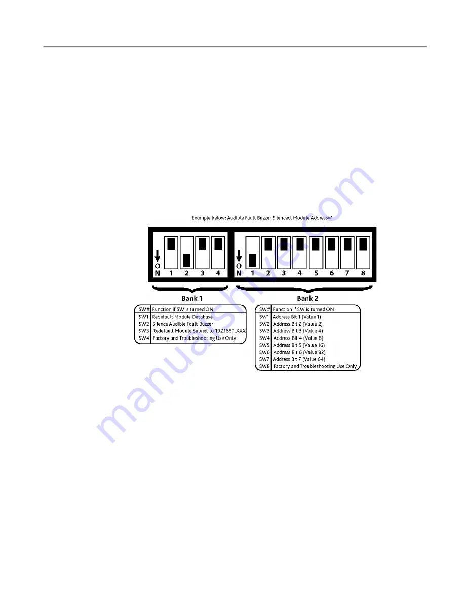
On the front of the NC120 CE Module, you will find a bank of DIP switches. These DIP switches are
used to configure various options on the CE module and to provide an address for the CE module.
Figure 2 - Module Dip Switch Addressing
The small bank of 4 DIP switches on the left is used for the following functions. Note that the down pos-
ition of the switch is on. Normal settings are indicated in parenthesis.
Switch 1
– Redefault the database. (Off/Up)
Switch 2
– Silence the audio alarm buzzer. (On/Down)
Switch 3
– Redefault network subnet assignment to 192.168.1. (Off/Up)
Switch 4
– Factory and troubleshooting use only. (Off/Up)
The second bank of 8 DIP switches is used to set the address of the NC120 CE Module.
Switch 1 – Switch 7
– Used to select the CE module’s address. Valid addresses are 1-75. Note that
though there are 75 available DIP switch addresses, no more than 20 modules may be installed on a
single Tek-CARE system. Switch 1- Switch 7 utilize standard binary addressing, with Switch 1 being 1
and Switch 7 being 64.
Switch 8
– Factory Use Only. (Leave turned Off/Up)
10
|
IL992 Tek-CARE120 Installation Manual
Copyright
©
TekTone Sound and Signal Mfg., Inc. All Rights Reserved


