


TEK-CPCI-1003 Technical Reference Manual
12-14
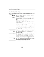
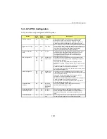
12.3.7 Integrated Peripherals
This part of the setup configures Integrated Peripherals options.
Option
BIOS
Default
Setup
Default
Possible
Settings
Description
IDE HDD Block Mode
Dis.
En.
En., Dis.
Block mode is also called block transfer, multiple commands, or
multiple sector read/write. If your IDE hard drive supports block
mode (most new drives do), select Enabled for automatic
detection of the optimal number of block read/writes per sector the
drive can support.
IDE
Primary/Secondary
Master/Slave PIO
Auto
Auto
Mode 0, Mode
1, Mode 2,
Mode 3, Mode
4, Auto
These options only appear if the On-Chip Primary/Secondary PCI
IDE options are enabled.
The four IDE PIO (Programmed Input/Output) fields let you set a
PIO mode (0-4) for each of the four IDE devices that the onboard
IDE interface supports. Modes 0 through 4 provide successively
increased performance and speed. In Auto mode, the system
automatically determines the best mode for each device. If you
select a mode that the drive does not support, it may not work, so
choose a lesser value or Auto to see the best mode for the drive.
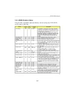
IDE
Primary/Secondary
Master/Slave UDMA
Dis.
Auto
Auto, Dis.
Ultra DMA/33 implementation is possible only if your IDE hard
drive supports it and the operating environment includes a DMA
driver (Windows 95 OSR2 or a third-party IDE bus master driver).
If your hard drive and your system software both support Ultra
DMA/33, select Auto to enable BIOS support.
On-Chip
Primary/Secondary
PCI IDE
En.
En.
En., Dis.
The integrated peripheral controller contains an IDE interface with
support for two IDE channels. Select Enabled to activate each
channel separately.
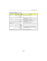
Onboard PCI SCSI
Chip
En.
En.
En., Dis.`
Enables/disables the onboard SCSI controller
Ethernet 1 and 2
En.
En.
En., Dis.
Enables/disables onboard Ethernet 1 or 2 controller.
USB Keyboard
Support
Dis.
Dis.
En., Dis.
Select Enabled, if your system contains an Universal Serial Bus
(USB) controller and you have an USB keyboard.
Note: This option is for DOS and BIOS support only (Win95
has its own drivers).
Onboard FDC
Controller
En.
En.
En., Dis.
Select Enabled if your system has a floppy disk controller (FDC)
installed on the system board and you wish to use it. If you install
an add-in FDC or the system has no floppy drive, select Disabled
in this field.
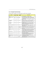
Onboard Serial Ports 1
and 3
Auto
Auto
Dis., Auto
3F8/IRQ4,
2F8/IRQ3,
3E8/IRQ4,
2E8/IRQ3,
Select a COM port address and IRQ# for the first and second
serial ports.
Onboard Serial Port 2
2F8
2F8
Dis.,
3E8, 2E8,
3F8, 2F8
Select a COM port address for the serial port #2.
IRQ Line
IRQ4
IRQ4
IRQ 3, 4, 5, 7
Select an IRQ line for the serial port #2.
Onboard Serial Port 4
3E8
3E8
Dis.,
3E8, 2E8,
3F8, 2F8
Select a COM port address for the serial port #4.
IRQ Line
IRQ3
IRQ3
IRQ 3, 4, 5, 7
Select an IRQ line for the serial port #4.
Serial Port 3 Mode
RS-232
RS-232
IrDA, RS-232,
RS-422, RS-
485
Select the operation mode for Serial Port 3.
...
Содержание TEK-CPCI 1003
Страница 15: ...TEK CPCI 1003 Technical Reference Manual 5 4 5 1 CONNECTOR LOCATION...
Страница 22: ...FEATURE DESCRIPTION 7 ONBOARD FEATURES...
Страница 51: ...TEK CPCI 1003 Technical Reference Manual 9 2 JUMPER LOCATION...
Страница 52: ...Setting Jumpers 9 3 JUMPER SETTINGS Table 1...
Страница 53: ...TEK CPCI 1003 Technical Reference Manual 9 4 JUMPER SETTINGS TABLE 2...
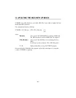
Страница 67: ...SOFTWARE SETUPS 12 AWARD SETUP PROGRAM 13 UPDATING THE BIOS WITH UPGBIOS 14 VT100 MODE...
Страница 95: ...C 1 C BOARD DIAGRAMS C 1 ASSEMBLY TOP DIAGRAM...


