TEK-CPCI-1003 Technical Reference Manual
5-6
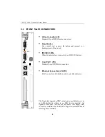
5.3 FRONT PLATE CONNECTORS
§
Video Connector (J8)
Standard 15-pin DSUB female connectors.
§
Reset Button
Use a small tool to press the button and proceed to a
hardware reset of the board.
§
IDE/SCSI LEDs
When lit indicate there is an activity on IDE/SCSI devices.
§
Com Port 1 (J10)
Standard 9-pin DSUB male connectors.
§
Ethernet Connectors (J12/J15)
RJ-45 connectors with built-in activity and link indicators.
The front plate supports a PMC cutout and a cap that also acts as
an EMI shield when there is no PMC device installed. An
optional front plate with mouse, keyboard, and floppy disk
cutouts is available from TEKNOR to support a mezzanine board
featuring these functions.
Содержание TEK-CPCI 1003
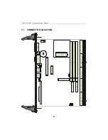
Страница 15: ...TEK CPCI 1003 Technical Reference Manual 5 4 5 1 CONNECTOR LOCATION...
Страница 22: ...FEATURE DESCRIPTION 7 ONBOARD FEATURES...
Страница 51: ...TEK CPCI 1003 Technical Reference Manual 9 2 JUMPER LOCATION...
Страница 52: ...Setting Jumpers 9 3 JUMPER SETTINGS Table 1...
Страница 53: ...TEK CPCI 1003 Technical Reference Manual 9 4 JUMPER SETTINGS TABLE 2...
Страница 67: ...SOFTWARE SETUPS 12 AWARD SETUP PROGRAM 13 UPDATING THE BIOS WITH UPGBIOS 14 VT100 MODE...
Страница 95: ...C 1 C BOARD DIAGRAMS C 1 ASSEMBLY TOP DIAGRAM...


