


12
www.teejet.com
Aeros 9040 Field Computer
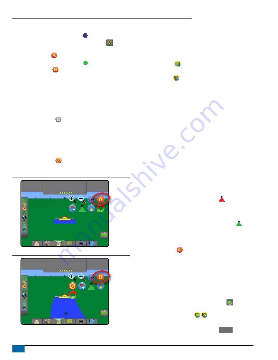
2) Establish an AB guideline
1. Drive to the desired location of Point A .
2. Press NAVIGATION AND GUIDANCE OPTIONS tab
to display
navigation options.
3. Press MARK A icon .
4. Drive to the desired location of Point B .
5. Press MARK B icon to establish the AB line.
6. “Would you like to name this guideline?”
Press:
►Yes – to enter a name and save the guideline in the console
►No – to automatically generate a name and save the guideline in
the console
The console will begin providing navigation information.
NOTE: The MARK B Icon is not available for selection (grayed out)
until the minimum distance is travelled (9.84 feet / 3.0 meters in
Straight or Curved guidance, 164.04 feet / 50.0 meters in Circle
Pivot guidance).
NOTE: It is not necessary to drive the entire circumference of the
center pivot in order to initiate Circle Pivot Guidance.
Use CANCEL MARK icon to cancel the Mark A command and
revert to the previous guideline (when established).
Figure 12: Mark A Point
1:12 pm
7.2
mph
Mark A
Figure 13: Mark B Point
1:14 pm
7.2
mph
Mark B
3) Create an Application Boundary
Available on any guidance screen, the Boundaries and polygons tab
displays exterior boundary, interior boundary and polygon options.
Application boundaries establish the work areas where product is or is
not applied while using ASC or BoomPilot.
• Exterior Boundary – establishes a work area where
application will be applied while using ASC or BoomPilot.
• Interior Boundary – establishes a work area where application
will NOT be applied while using ASC or BoomPilot.
Boundaries can be established in all guidance modes. Up to 100 total
exterior boundary and/or interior boundaries can be stored within a
single job. Application is not required to map a boundary.
Using Data -> Job Data -> Manage or with Fieldware Link, a user can
duplicate and edit jobs for reuse of boundaries for different applications
over the same field.
Application is not required to map a boundary or polygon.
If mapping a boundary or polygon with one or more sections folded
in and turned off, it is necessary to maintain this section configuration
for the duration of the boundary or polygon pass. Any changes made
to the number of sections turned on, and therefore the width of the
machine after the boundary or polygon mapping process has started,
will result in the application mapping the boundary or polygon at the
outer edge of all the programmed sections – not necessarily those
turned on at any given time during the boundary or polygon pass.
When mapping a boundary or polygon with some sections turned off,
it is necessary to turn BoomPilot to Manual mode and turn ON the
master and section switches for all sections that will be used during
the boundary or polygon pass. Once the boundary or polygon pass
is complete the sections switches can be turned OFF, master switch
remains ON, BoomPilot can be returned to Automatic mode and
automatic section control can then be used.
NOTE: If a boundary is mapped with some sections folded
as described above, it may be necessary to use the
A+ NUDGE icon on the guideline over to the correct
position for subsequent passes in the field.
Establishing an Exterior or Interior Boundary
To establish an exterior or interior boundary:
1. Drive to a desired location at the perimeter of the application
area and orientate the vehicle in association to the established
mapping location.
2. Press BOUNDARY AND POLYGON OPTIONS tab
to display
boundary and polygon options.
3. Press MARK BOUNDARY icon .
4. Verify that the Mapping location is correct.
◄If the Mapping location is not correct, press
Cancel
then go to
Configuration-> Mapping and guidance-> Mapping location.


