


9
98-01504-ENUS R2
Aeros 9040 Field Computer
4) Set Up the Mapping Location
Mapping location establishes the location from which boundary and
polygon mapping will take place.
1. Press CONFIGURATION side tab
.
2. Press
Mapping and Guidance
.
3. Select from:
►Mapping Location – establishes the layout of the location from
which the boundary or polygon will be mapped.
● Default Location – While creating an exterior boundary or
polygon, the line will be to the exterior of the outermost active
section. While creating an interior boundary, the line will be
to the interior of the innermost active section. If no sections
are active, the boundary will be marked to the end of the
outermost section.
● User Entry – in-line and lateral offset from the GNSS antenna
directions and distances can be specified by the user. Up
to five (5) user entries can be created. See “User Entered
Mapping Location” for details.
►Guidance Width – used to set the distance between guidelines
►Guidance Sensitivity – sets the distance around the guideline that
is perceived as zero error.
4. Select user entry location from the Mapping Locations drop-down
options.
5. Press MAPPING LOCATION NEXT PAGE arrow to set up the
selected specific mapping location options.
6. Select:
►Location Name – used to enter the name of the mapping location
for the current user entry selected
►Mapping Location In-line Offset Direction – used to select
whether the mapping location is located in front of or behind the
GNSS antenna as the vehicle moves in a forward direction
►Mapping Location In-line Offset Distance – used to define the in-
line distance from the GNSS antenna to the mapping location
►Mapping Location Lateral Offset Direction – used to select
the lateral direction from the centerline of the machine to the
mapping location while facing in the machine’s forward direction
►Mapping Location Lateral Offset Distance – used to define
the lateral distance from the centerline of the machine to the
mapping location
7. Press RETURN arrow
to return to the Mapping and Guidance
screen or CONFIGURATION side tab
to return to the main
Configuration screen.
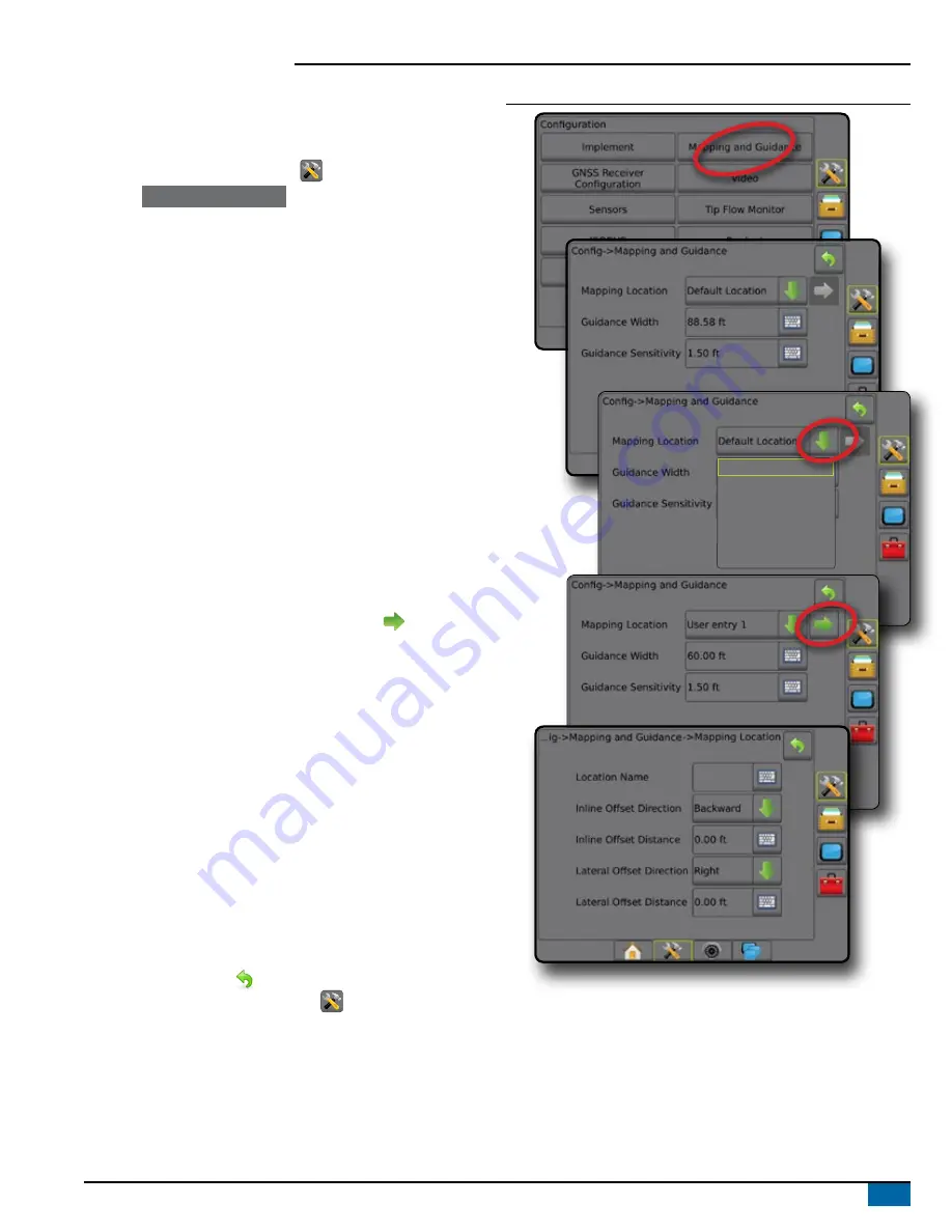
Figure 10: User Entered Mapping Location
Default Location
User Entry 1
User Entry 2
User Entry 3
User Entry 4
User Entry 5


